Special Tools
J 36660-A Electronic Torque Angle Meter
Removal Procedure
- Disconnect the negative battery cable. Refer to Battery Negative Cable Disconnection and Connection .
- Drain the engine coolant. Refer to Cooling System Draining and Filling .
- Remove the engine cooling fan assembly. Refer to Fan Clutch Replacement .
- Remove the drive belt. Refer to Drive Belt Replacement .
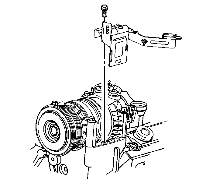
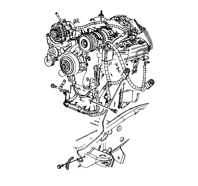
- Remove the bolt holding the positive battery cable junction block bracket to the power steering pump mounting bracket.
- Move the bracket with the wiring harness and the junction block aside.
- Move the battery positive and negative cables aside.
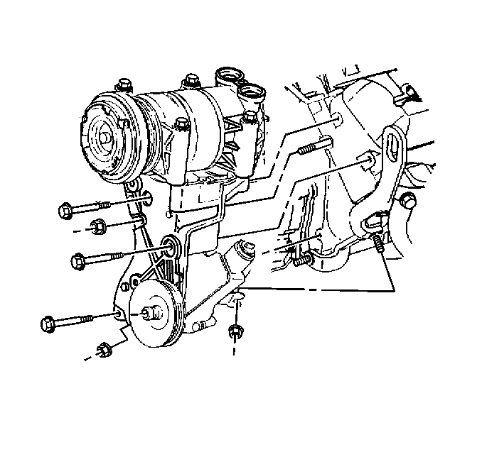
- Loosen the nut holding the power steering pump rear bracket to the side of the engine.
- Remove the nut holding the power steering pump rear bracket to the front of the engine
- Remove the three bolts and the nut holding the power steering pump mounting bracket to the engine.
- With the power steering pump and the A/C compressor still attach, slide the power steering pump mount bracket off of the stud and set aside.
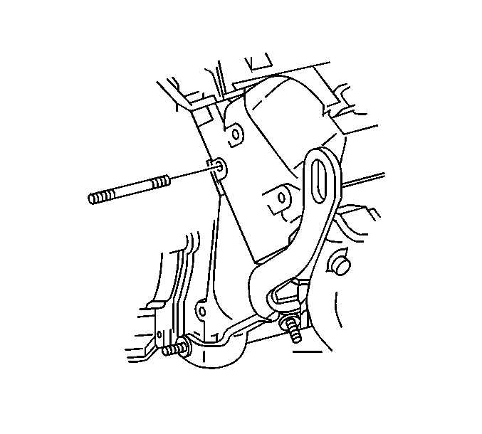
- Remove the power steering pump mounting bracket stud from the cylinder head.
- Remove the lower intake manifold. Refer to Lower Intake Manifold Replacement .
- Remove the exhaust manifold. Refer to Exhaust Manifold Replacement - Left Side .
- Remove the push rods. Refer to Valve Rocker Arm and Push Rod Replacement .
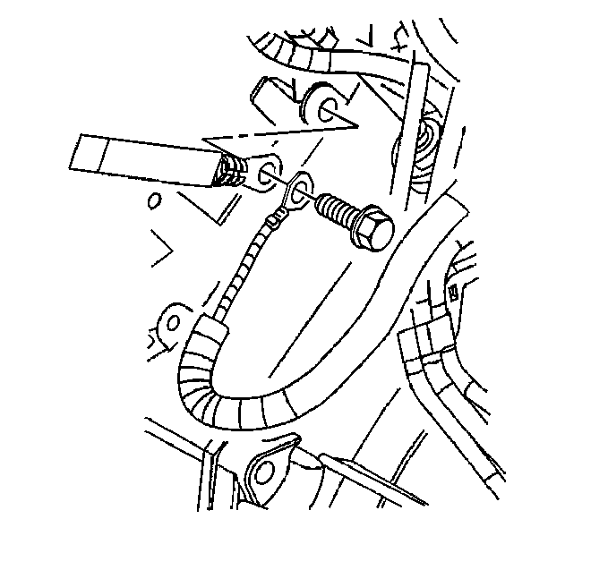
- Remove the ground strap and ground wire bolt from the rear of the cylinder head.
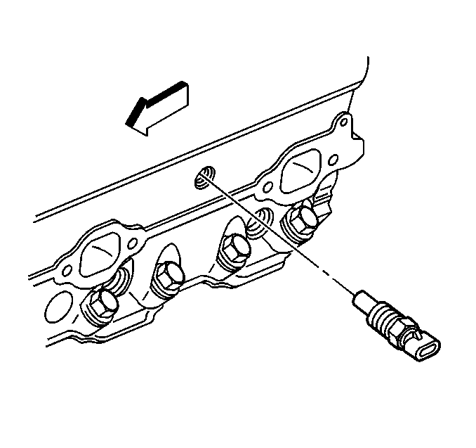
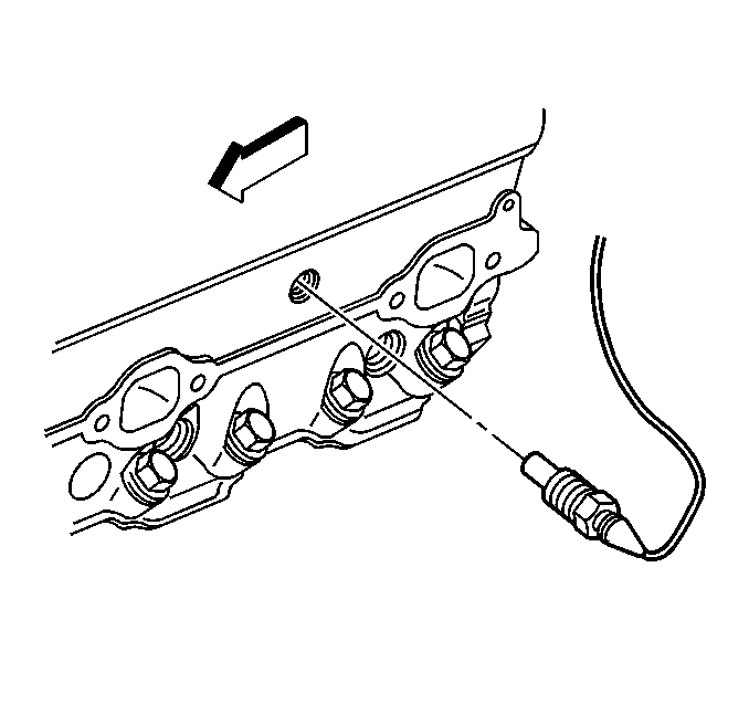
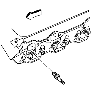
- Remove the engine coolant temperature sensor (if applicable).
- Remove the engine coolant temperature gauge sensor (if applicable).
- Remove the spark plugs.
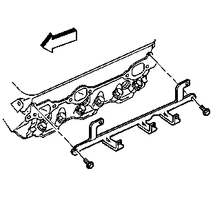
- Remove the bolts and the spark plug wire support.
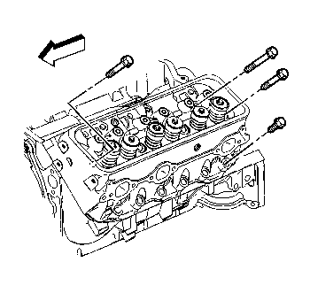
- Remove and discard the cylinder head bolts.
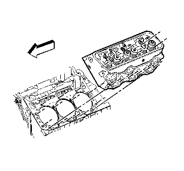
- Remove the cylinder head.
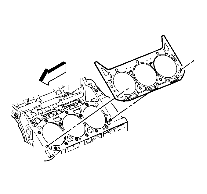
- Remove and discard the cylinder head gasket.
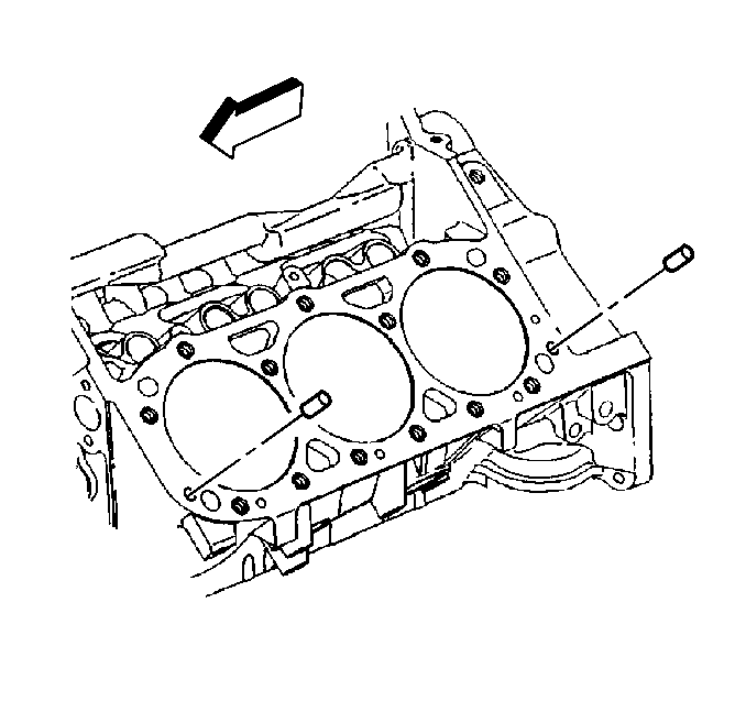
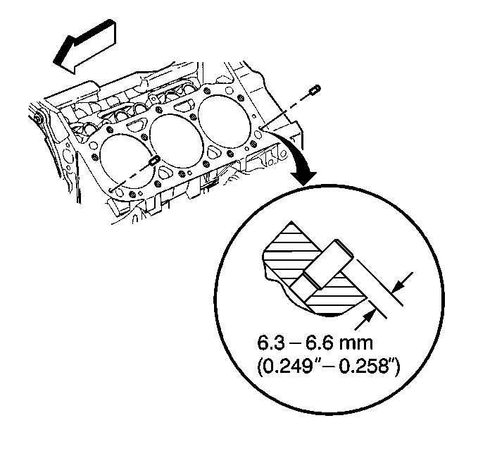
- Remove the dowel pins (cylinder head locator) (if required).
- Clean the engine block and the cylinder head sealing surfaces.
- Clean the engine block bolt holes.
- For further service to the cylinder head refer to the following:
Notice: Clean all dirt, debris, and coolant from the engine block cylinder head bolt holes. Failure to remove all foreign material may result in damaged threads, improperly tightened fasteners or damage to components.
| • | Refer to Cylinder Head Disassemble in Engine Unit Repair Manual. |
| • | Refer to Cylinder Head Cleaning and Inspection in Engine Unit Repair Manual. |
| • | Refer to Valve Guide Reaming, and Valve and Seat Grinding in Engine Unit Repair Manual. |
| • | Refer to Cylinder Head Assemble in Engine Unit Repair Manual. |
Installation Procedure
- Clean the cylinder head gasket surfaces on the engine block.
- Inspect the dowel pins (cylinder head locator) for proper installation.
- Clean the cylinder head gasket surfaces on the cylinder head.
- Install the NEW cylinder head gasket in position over the dowel pins (cylinder head locator).
- Install the cylinder head onto the engine block.
- Apply sealant GM P/N 12346004 or equivalent to the threads of the NEW cylinder head bolts.
- Install the cylinder head bolts finger tight.
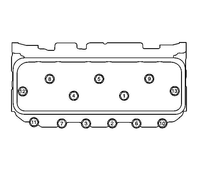
- Tighten the cylinder head bolts in sequence on the first pass.
- Use the in order to tighten the cylinder head bolts in sequence on the final pass.
- Install the spark plug wire support and bolts.
- Measure the NEW spark plugs for the proper gap.
- Install the spark plugs.
- If reusing the engine coolant temperature gauge sensor (if applicable), apply sealant GM P/N 12346004 or equivalent to the threads of the engine coolant temperature gage sensor.
- Install the engine coolant temperature gage sensor (if applicable).
- If reusing the engine coolant temperature sensor (if applicable), apply sealant GM P/N 12346004, or equivalent to the threads of the engine coolant temperature gage sensor.
- Install the engine coolant temperature sensor (if applicable).
- Install the ground strap and the ground wire bolt.
- Install the valve pushrods. Refer to Valve Rocker Arm and Push Rod Replacement .
- Install the lower intake manifold. Refer to Lower Intake Manifold Replacement .
- Install the exhaust manifold. Refer to Exhaust Manifold Replacement - Left Side .
- Install the stud for the power steering pump mounting bracket to the cylinder head.
- Slide the power steering pump mounting bracket with the power steering pump and the A/C compressor on the stud.
- Position the power steering pump rear bracket on the studs.
- Install the power steering pump mounting bracket three bolts and the nut.
- Install the nut for the power steering pump rear bracket to the front of the engine.
- Position the battery positive and negative cables.
- Install the battery positive cable junction block bracket and bolt to the power steering pump mounting bracket.
- Install the engine cooling fan assembly. Refer to Fan Clutch Replacement .
- Install the drive belt. Refer to Drive Belt Replacement .
- Fill the engine cooling system. Refer to Cooling System Draining and Filling .
- Connect the battery negative cable. Refer to Battery Negative Cable Disconnection and Connection .
Important: Do not use any type sealer on the cylinder head gasket (unless specified).
Guide the cylinder head carefully into place over the dowel pins and the cylinder head gasket.
Notice: Refer to Fastener Notice in the Preface section.
Tighten
Tighten the bolts in sequence on the first pass to 30 N·m (22 lb ft).
Tighten
| • | Tighten the long bolts (1, 4, 5, 8, 9) on the final pass in sequence to 75 degrees. |
| • | Tighten the medium bolts (12, 13) on the final pass in sequence to 65 degrees. |
| • | Tighten the short bolts (2, 3, 6, 7, 10, 11) on the final pass in sequence to 55 degrees. |
Tighten
Tighten the spark plug wire support bolts to 12 N·m (106 lb in).
Adjust the spark plug gap if necessary.
Specification
Spark plug gap to 1.52 mm (0.060 in).
Tighten
| • | Tighten the spark plugs for a USED cylinder head to 15 N·m (11 lb ft). |
| • | Tighten the spark plugs for the initial installation of a NEW cylinder head to 30 N·m (22 lb ft). |
Tighten
Tighten the engine coolant temperature gauge sensor to 20 N·m (15 lb ft).
Tighten
Tighten the engine coolant temperature sensor to 20 N·m (15 lb ft).
Tighten
Tighten the bolt to 16 N·m (12 lb ft).
Tighten
Tighten the power steering pump mounting bracket stud to 20 N·m (15 lb ft).
Tighten
Tighten the power steering pump mounting bracket and the power steering pump rear bracket bolts and the nuts to 41 N·m (30 lb ft).
Do not connect the negative battery cable to the battery.
Tighten
Tighten the junction block bracket bolt to 25 N·m (18 lb ft).
