Cleaning Procedure
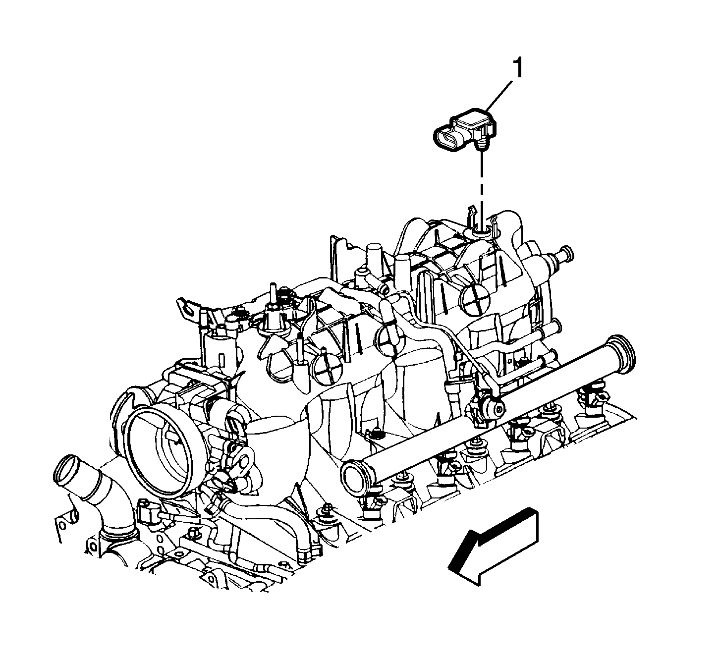
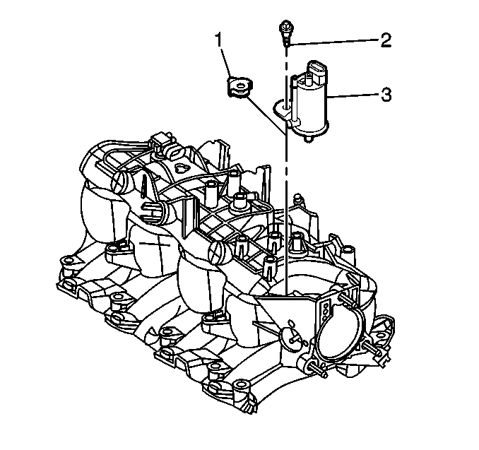
- Remove the Manifold Absolute Pressure (MAP) sensor (1) from the rear of the intake. The MAP sensor is to be reinstalled upon completion of the cleaning and inspection procedures.
- Inspect the sealing grommet on the MAP sensor. The grommet should not be torn or damaged.
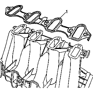
- Remove and discard the intake manifold-to-cylinder head gaskets (1).
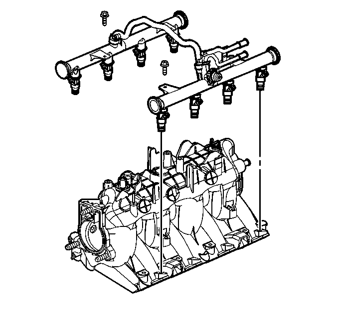
- Remove the fuel rail with injectors. Refer to Fuel Rail and Injectors Removal .
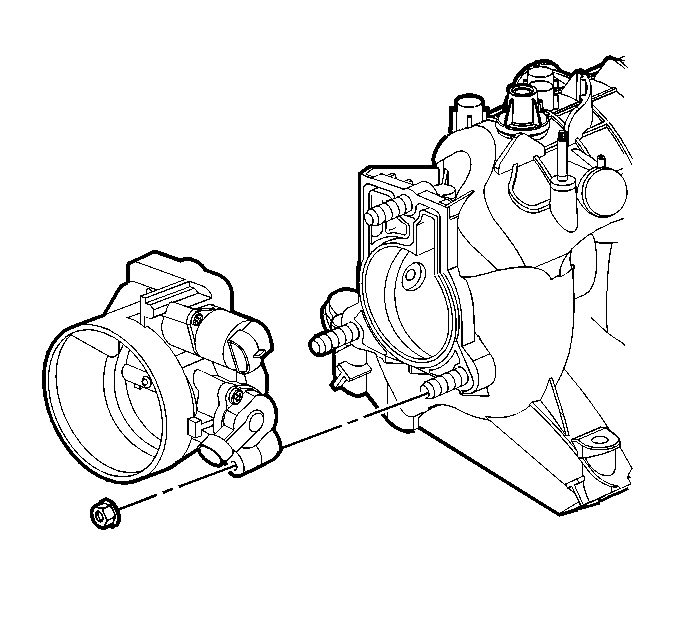
- Remove the throttle body and gasket. Refer to Throttle Body Removal .
- Remove the Evaporative Emissions (EVAP) purge solenoid (3), bolt (2), and isolator (1).
- Clean the intake manifold in solvent.
- Dry the intake manifold with compressed air.
Important: Do not reuse the intake manifold-to-cylinder head sealing gaskets.
| • | Clean the intake manifold gasket surfaces. |
| • | Clean the intake manifold internal passages. |
Caution: Wear safety glasses in order to avoid eye damage.
Inspection Procedure
- Inspect the throttle body studs and threaded inserts for looseness or damaged threads.
- Inspect the wire harness stud and threaded insert for looseness or damaged threads.
- Inspect the fuel rail bolt inserts for looseness or damaged threads.
- Inspect the intake manifold vacuum passages for debris or restrictions.
- Inspect for damaged or broken vacuum fittings, damaged MAP sensor (1) mounting bore, or broken MAP sensor retaining tabs.
- Inspect the composite intake manifold assembly for cracks or other damage.
- Inspect all the gasket sealing surfaces for damage.
- Inspect the fuel injector bores for excessive scoring or damage.
- Inspect the intake manifold cylinder head deck for warpage.
- Install the MAP sensor (1).
- Install the EVAP solenoid, bolt, and isolator.


Inspect the areas between the intake runners.
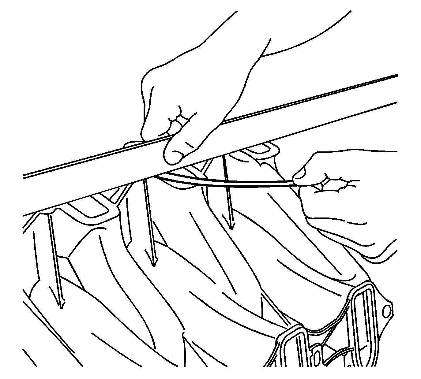
| 9.1. | Locate a straight edge across the intake manifold cylinder head deck surface. |
Position the straight edge across a minimum of two runner port openings.
| 9.2. | Insert a feeler gage between the intake manifold and the straight edge. |
A intake manifold with warpage in excess of 3 mm (0.118 in) over a 200 mm (7.87 in) area is warped and should be replaced.

Notice: Use the correct fastener in the correct location. Replacement fasteners must be the correct part number for that application. Fasteners requiring replacement or fasteners requiring the use of thread locking compound or sealant are identified in the service procedure. Do not use paints, lubricants, or corrosion inhibitors on fasteners or fastener joint surfaces unless specified. These coatings affect fastener torque and joint clamping force and may damage the fastener. Use the correct tightening sequence and specifications when installing fasteners in order to avoid damage to parts and systems.
Tighten
Tighten the EVAP solenoid bolt to 10 N·m (89 lb in).
