For 1990-2009 cars only
Removal Procedure
- Disable the SIR system. Refer to Disabling the SIR System .
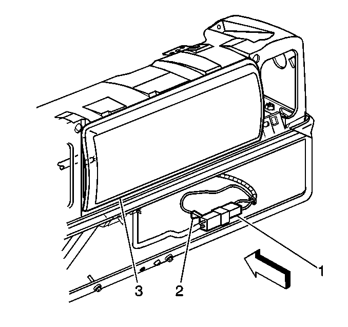
- Open the instrument panel compartment door, lift stop and allow door to fully open.
- Remove the yellow 2-way electrical harness connector at the left side of the mounting bracket.
- Remove the connector position assurance (CPA) (3) from the yellow 2-way electrical harness connector.
- Remove the inflatable restraint IP module yellow pigtail connector from the yellow 2-way electrical harness connector (2).
- Remove the fasteners attaching the inflatable restraint IP module to the mounting bracket.
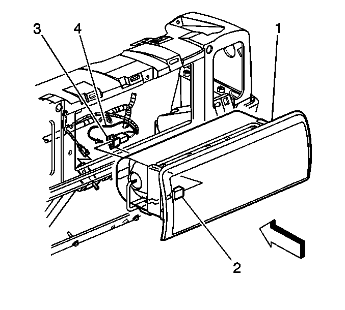
- Remove the inflatable restraint IP module from the front of the instrument panel (1). Ensure that you keep a firm hold of the module.
- Fully deploy the module before disposal. If the module was replaced under warranty, fully deploy and dispose of the module after the required retention period. Refer to Inflator Module Handling, Shipping, and Scrapping .
Installation Procedure
- Install the inflatable restraint IP module (1) to the mounting bracket through the front of the instrument panel.
- Install the fasteners to the inflatable restraint IP module.
- Install the inflatable restraint IP module yellow pigtail connector to the yellow 2-way electrical harness connector (2).
- Install the connector position assurance (3).
- Install the yellow 2-way electrical harness connector to the mounting on the left side of the mounting bracket.
- Close the instrument panel compartment door.
- Enable the SIR system. Refer to Enabling the SIR System .
Notice: Use the correct fastener in the correct location. Replacement fasteners must be the correct part number for that application. Fasteners requiring replacement or fasteners requiring the use of thread locking compound or sealant are identified in the service procedure. Do not use paints, lubricants, or corrosion inhibitors on fasteners or fastener joint surfaces unless specified. These coatings affect fastener torque and joint clamping force and may damage the fastener. Use the correct tightening sequence and specifications when installing fasteners in order to avoid damage to parts and systems.
Tighten
Tighten the fasteners to 9 N·m (80 lb in).
