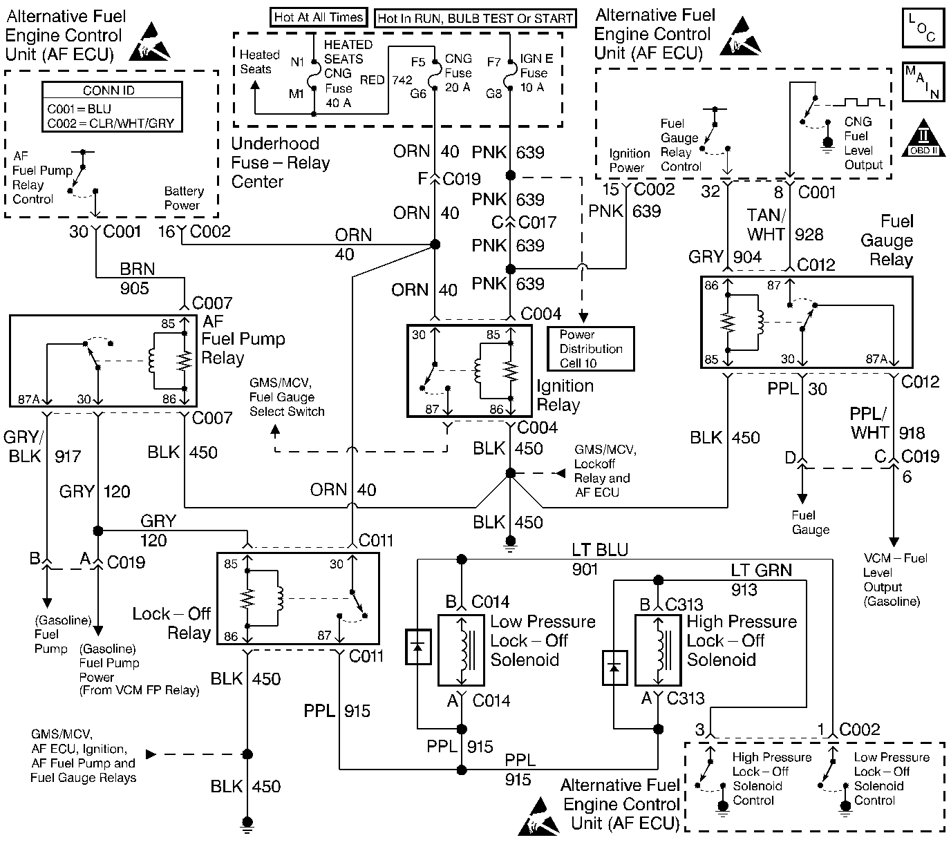
Circuit Description
The ignition relay is the positive voltage supply source for the following components:
| • | the gas mass sensor/mixture control valve (GMS/MCV) |
| • | the fuel gauge select switch |
The ignition relay coil is energized when the ignition switch is turned to the run or start positions. The ignition relay switch contact is supplied voltage at all times.
Test Description
The number(s) below refer to the step number(s) on the diagnostic table.
-
The AF Powertrain OBD System Check MUST be performed before proceeding with this diagnostic table. Failure to perform the OBD System Check will result in mis-diagnosis.
-
This step checks the AF ECU fuses for opens and also checks the voltage supply to the fuses.
-
This step checks if the AF ECU is powered-up.
-
This step checks the battery positive and switched ignition voltage circuits to the AF ECU.
-
This step checks the AF ECU ground circuits.
-
This step checks for proper operation of the FIL. If the FIL illuminates then the ignition relay is ON.
-
This step checks the ignition relays ability to turn OFF.
-
This step checks the ignition relay coils ground circuit. If the test lamp illuminates then the ignition relay must be faulty.
-
This step indicates the components or circuits that may have caused a fuse to blow. Some components may require they be turned ON in order to blow the fuse. An example would be depressing the fuel gauge select switch in order to test the select switch circuit for a short.
Step | Action | Value(s) | Yes | No | ||||||||||||||||
|---|---|---|---|---|---|---|---|---|---|---|---|---|---|---|---|---|---|---|---|---|
Were you sent here from the AF Powertrain On-Board Diagnostic (OBD) System Check? | -- | Go to Alternative Fuels (AF) Powertrain On Board (OBD) System Check | ||||||||||||||||||
2 |
Is either fuse open (blown) ? | -- | ||||||||||||||||||
Ignition ON engine OFF. Probe both terminals of each fuse using the J 35616-200 Un-powered Test Lamp connected to a known good ground. With the fuses installed the probe test points for the fuses are visible at either side of the amperage rating. Does the test lamp illuminate at all terminals? | -- | |||||||||||||||||||
4 |
Are all repairs complete? | -- | -- | |||||||||||||||||
Using a scan tool attempt to communicate and retrieve data from the alternative fuels engine control unit (AF ECU). Does the scan tool display AF ECU data? | -- | |||||||||||||||||||
Does the test lamp illuminate at both terminals? | -- | |||||||||||||||||||
Probe all the ECU Ground circuit terminals at the AF ECU connectors with the test lamp connected to BATTERY POSITIVE. Does the test lamp illuminate at all terminals? | -- | |||||||||||||||||||
Did the FIL illuminate for a two second bulb check or stay ON? | -- | |||||||||||||||||||
9 | With the ignition ON, backprobe the ignition relay switch load terminal (87) with the test lamp connected to a known good ground. Is the test lamp illuminated? | -- | Go to Fuel Gauge Selector Switch/Fuel Indicator Lamp Diagnosis | |||||||||||||||||
Is the test lamp illuminated with the ignition OFF? | -- | Go to Alternative Fuels (AF) Powertrain On Board (OBD) System Check | ||||||||||||||||||
11 | With the ignition ON, backprobe the ignition relay switch supply terminal (30) with the test lamp connected to a known good ground. Is the test lamp illuminated? | -- | ||||||||||||||||||
12 | With the ignition ON, backprobe the ignition relay coil supply terminal (85) with the test lamp connected to a known good ground. Is the test lamp illuminated? | -- | ||||||||||||||||||
Is the test lamp illuminated? | -- | |||||||||||||||||||
Is the repair or replacement complete? | -- | -- | ||||||||||||||||||
15 | Repair the open in the AF ECU circuit that did not light the test lamp. Is the repair complete? | -- | -- | |||||||||||||||||
16 | Replace the stuck ignition relay or repair the Ignition Power circuit (relay terminal 85) shorted to battery positive. Is the repair or replacement complete? | -- | -- | |||||||||||||||||
17 | Repair the open in the ignition relay switch supply circuit terminal (30) between the relay and the circuit splice. Is the repair complete? | -- | -- | |||||||||||||||||
18 | Repair the open in the ignition relay coil supply circuit terminal (85) between the relay and the circuit splice. Is the repair complete? | -- | -- | |||||||||||||||||
19 | Repair the open in the ignition relay coil ground circuit terminal (86) between the relay and ground. Is the repair complete? | -- | -- | |||||||||||||||||
20 | Replace the ignition relay. Is the replacement complete? | -- | -- | |||||||||||||||||
21 | Check AF ECU terminal contact. Repair terminal contact as necessary. Was terminal contact repaired? | -- | ||||||||||||||||||
22 | Replace the AF ECU. Refer to Engine Control Unit Replacement . Is the replacement complete? | -- | -- | |||||||||||||||||
23 |
Does the vehicle operate on CNG with normal driveability, no FIL/MIL illumination and no stored DTCs? | -- | System OK | Go to Alternative Fuels (AF) Powertrain On Board (OBD) System Check |
