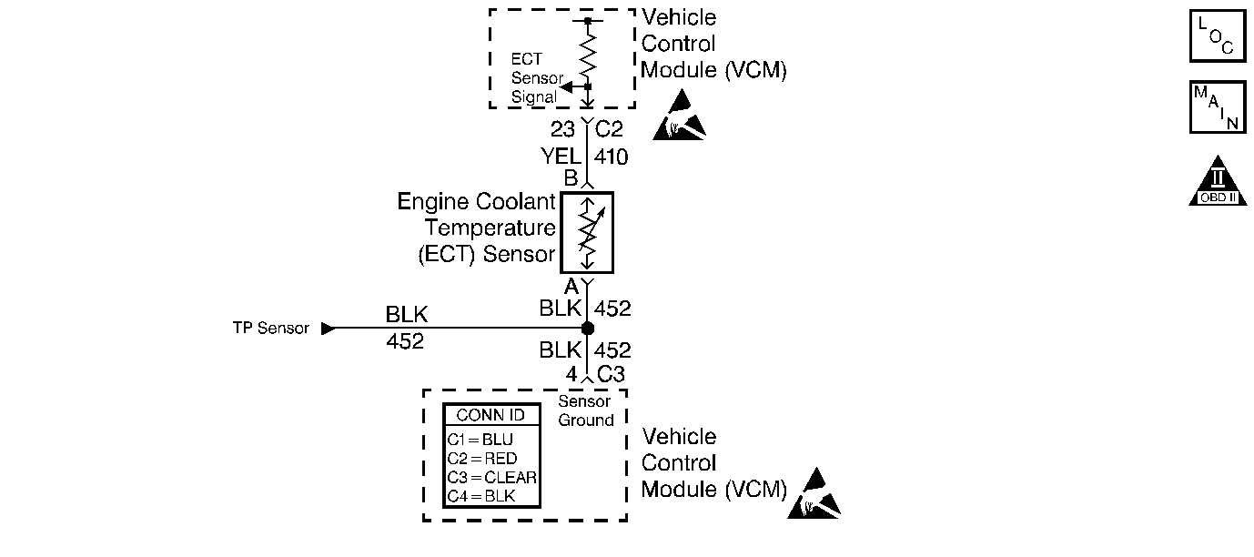
Circuit Description
The engine coolant temperature (ECT) sensor is a thermistor. The control module supplies the ECT sensor with a reference voltage on the ECT signal circuit and a ground circuit. When the ECT sensor resistance is high, indicating a cold sensor, the ECT sensor signal voltage remains near the supplied voltage. The ECT sensor decreases the signal voltage as the ECT sensor resistance is low, indicating a warm sensor. The control module monitors the ECT sensor signal circuit voltage in order to calculate the engine temperature.
This DTC is designed to detect an ECT sensor signal voltage higher than the possible range of a normally operating ECT sensor.
Conditions for Running the DTC
The engine run time is more than 5 seconds
Conditions for Setting the DTC
The ECT signal voltage is more than 4.90 volts for more than 20 seconds.
Action Taken When the DTC Sets
| • | The control module illuminates the malfunction indicator lamp (MIL) if a failure is detected during 2 consecutive key cycles. |
| • | The control module sets the DTC and records the operating conditions at the time the diagnostic failed. The failure information is stored in the scan tool Freeze Frame/Failure Records. |
Conditions for Clearing the MIL or DTC
| • | The control module turns OFF the MIL after 3 consecutive drive trips when the test has run and passed. |
| • | A history DTC will clear if no fault conditions have been detected for 40 warm-up cycles. A warm-up cycle occurs when the coolant temperature has risen 22°C (40°F) from the startup coolant temperature and the engine coolant reaches a temperature that is more than 70°C (158°F) during the same ignition cycle. |
| • | Use a scan tool in order to clear the DTCs. |
Diagnostic Aids
After starting the engine, the ECT sensor temperature should rise steadily to about 90°C (194°F), then stabilize when the thermostat opens. Check for an intermittent open or short to battery voltage in the ECT sensor signal circuit. This may be accomplished by moving the VCM harness at various locations while monitoring the ECT temperature and voltage on the scan tool. If the voltage varies, look for an open or short to voltage in the area of the harness that caused the variance.
Use the Temperature vs Resistance Value table in order to test the ECT sensor at various temperature levels in order to evaluate the possibility of a skewed (mis-scaled) sensor. A skewed sensor could result in poor driveability complaints. Refer to Temperature vs Resistance .
An intermittent may be caused by any of the following conditions:
| • | A poor connection |
| • | Rubbed through wire insulation |
| • | A broken wire inside the insulation |
Thoroughly check any circuitry that is suspected of causing the intermittent complaint. Refer to Intermittents and Poor Connections Diagnosis in Wiring Systems.
If a repair is necessary, refer to Wiring Repairs or Connector Repairs in Wiring Systems.
Test Description
The numbers below refer to the step numbers on the diagnostic table.
-
If the condition is present, the ECT sensor voltage measures more than 4.9 volts.
-
This test simulates the conditions for a DTC P0117. If the VCM recognizes the grounded circuit (low voltage) and displays a low voltage message, the VCM and the wiring are okay.
-
This test checks for an open or grounded ECT sensor signal circuit. Also being checked are the ECT sensor ground circuit and the VCM.
-
This test checks for a short to voltage on the ECT sensor signal circuit.
-
After repairing a short to voltage, it is necessary to recheck the operation of the ECT sensor.
Step | Action | Value(s) | Yes | No |
|---|---|---|---|---|
1 |
Important: Before clearing DTCs, use the scan tool Capture Info to save the Freeze Frame and Failure Records for reference. The control module's data is deleted once the Clear Info function is used. Did you perform the Powertrain On-Board Diagnostic (OBD) System Check? | -- | ||
Does the scan tool display an ECT sensor voltage more than the specified value? | 4.9 V | |||
Does the scan tool display an ECT sensor voltage less than the specified value? | 0.82 V | |||
Jumper the ECT sensor signal circuit to a ground. Does the scan tool display an ECT sensor voltage less than the specified value? | 0.82 V | |||
Is the voltage more than the specified value? | 5.20 V | |||
6 | The DTC is intermittent. Are any additional DTCs stored? | -- | Go to the applicable DTC table | Go to Diagnostic Aids |
7 | Check the ECT sensor harness connector and the VCM connector for a poor connection. Did you find a problem? | -- | ||
8 | Check the ECT sensor ground circuit for an open or poor connection between the ECT sensor and the VCM. Did you find a problem? | -- | ||
9 | Check the ECT sensor signal circuit for an open or poor connection between the ECT sensor and the VCM. Did you find a problem? | -- | ||
10 | Repair the short to voltage in the ECT sensor signal circuit. Refer to Wiring Repairs in Wiring Systems. Is the action complete? | -- | -- | |
11 | Repair the circuit as necessary. Refer to Wiring Repairs or Connector Repairs in Wiring Systems. Is the action complete? | -- | -- | |
Does the scan tool display an ECT sensor voltage less than the specified value? | 4.9 V | |||
13 | Replace the ECT sensor. Refer to Engine Coolant Temperature Sensor Replacement . Is the action complete? | -- | -- | |
14 |
Refer to Crankshaft Position System Variation Learn . Is the action complete? | -- | -- | |
15 |
Does the scan tool indicate the diagnostic Passed? | -- | ||
16 | Does the scan tool display any additional undiagnosed DTCs? | -- | Go to the applicable DTC table | System OK |
