FRONT WHEEL SLIDE-MODIFY BRAKE VALVE W/10,000-12,000 GVW

SUBJECT: FRONT WHEEL SLIDE (MODIFY BRAKE COMBINATION VALVE)
VEHICLES AFFECTED: 1988-92 C3, K3 TRUCK WITH 10,000-12,000 GVW (JB8 BRAKES)
Owners of some 1988-1992 C3 and K3 trucks with JB8 Brakes (10,000-12,000 # GVW) with certain rear heavy chassis cab applications, particularly wreckers with wheel lift attachments, may experience incidents of front wheel slide.
This condition may occur because the weight distribution on the front and rear axles changes when a vehicle is being towed due to the leverage exerted by the wheel lift mechanism. It is generally advisable to have a minimum of 20% of the gross vehicle weight on the front axle.
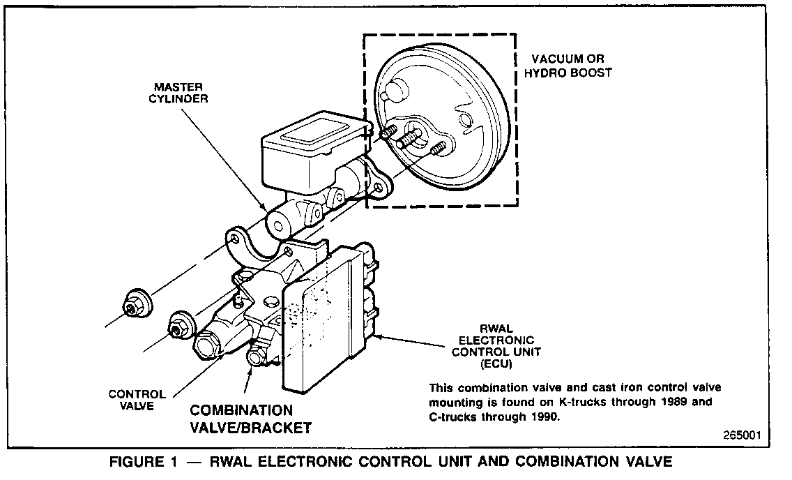
Weight distribution and stopping ability can be improved by applying more weight to the front axle and/or increasing rear brake output relative to front brake output. To improve the weight distribution, front bumper weights should be used and loads should be carried as far forward as possible while remaining within the gross axle and gross vehicle weight ratings. Increasing rear brake pressure will increase the rear brake output to match braking capability with the existing weight distribution. This may be accomplished by removing a seal in the rear brake proportioning section of the brake combination valve (Figure 1).
NOTE: If the wrecker body or any other applicable rear heavy body is ever removed where the vehicle would no longer be in a rear heavy condition, the proportioning valve should be returned to its original condition to prevent increased RWAL (Rear Wheel Anti-Lock) activation.
Stiffer rear springs will also help stabilize the vehicle and improve stopping ability.
SERVICE PROCEDURE:
Modifying the Brake Combination Valve to Increase Rear Brake Pressure
1. Remove the RWAL Electronic Control Unit from its mounting bracket and locate the combination valve which contains the proportioning valve (Figure 1).
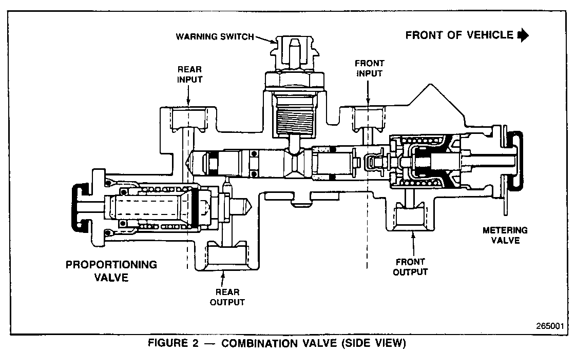
2. Carefully remove the nut located on the end of the proportioning valve located nearest the front of the dash. The nut is under spring pressure and care must be exercised so that the nut, the sealing O-ring or the spring is not lost (Figure 2).
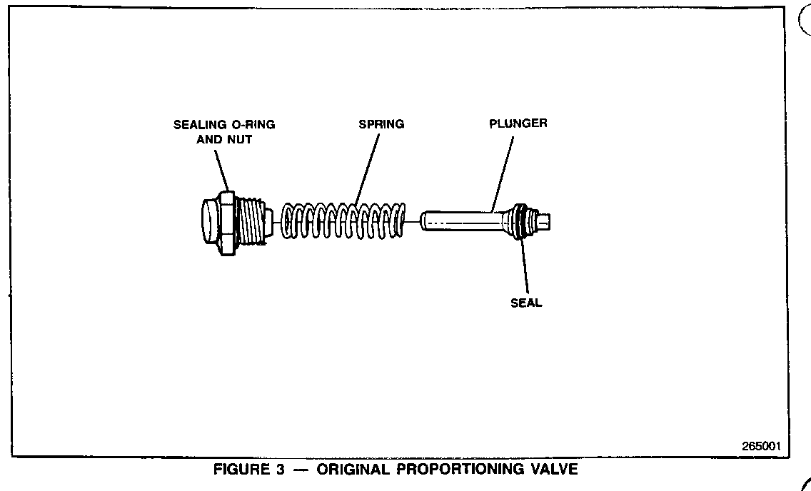
3. Remove the spring and plunger from the valve assembly (Figure 3).
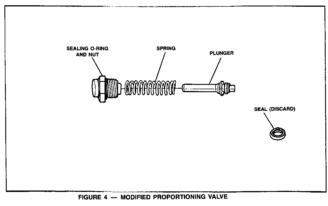
4. Remove the seal from the end of the plunger and discard the seal (Figure 4).
5. Install the plunger, spring, and nut in the reverse sequence making certain that the sealing O-ring is properly installed on the nut.
6. Torque the nut to 16-27 N.m. (12-20 lbs. ft.).
7. Bleed the rear brakes and pump brake pedal to verify proper bleed.
8. Install the RWAL Electronic Control Unit in its mounting bracket and road test vehicle to assure proper operation.
For vehicles repaired under warranty use:
Labor Time: 0.4 hrs.


General Motors bulletins are intended for use by professional technicians, not a "do-it-yourselfer". They are written to inform those technicians of conditions that may occur on some vehicles, or to provide information that could assist in the proper service of a vehicle. Properly trained technicians have the equipment, tools, safety instructions and know-how to do a job properly and safely. If a condition is described, do not assume that the bulletin applies to your vehicle, or that your vehicle will have that condition. See a General Motors dealer servicing your brand of General Motors vehicle for information on whether your vehicle may benefit from the information.
