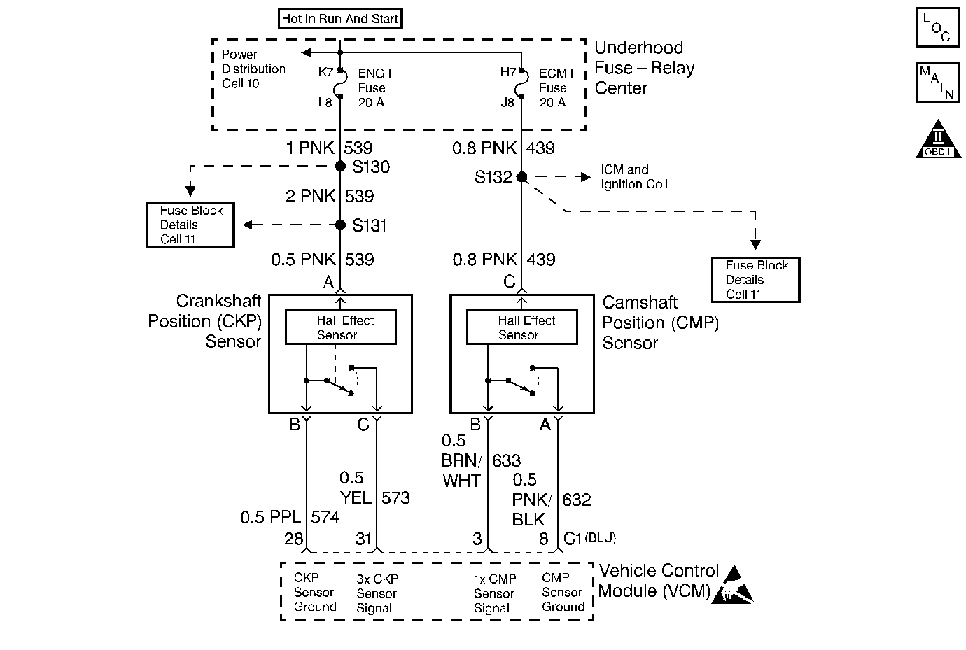
Circuit Description
The Camshaft Position (CMP) sensor is used to indicate the camshaft position. The VCM uses the CMP sensor in order to determine which cylinder is misfiring. This DTC is also used to check for a properly installed High Voltage switch. This is a type B DTC.
Conditions for Setting the DTC
The DTC will set if the engine is running and the cam sensor reference pulse is not seen once every 6 cylinders.
Action Taken When the DTC Sets
The VCM will turn ON the MIL after 2 consecutive driving cycles with the fault active.
Conditions for Clearing the MIL/DTC
The VCM turns OFF the MIL after 3 consecutive driving trips without a fault condition present. A history DTC will clear if no fault conditions have been detected for 40 warm-up cycles (the coolant temperature has risen 22°C (40°F) from the start-up coolant temperature and the engine coolant temperature exceeds 71°C (160°F) during that same ignition cycle) or the scan tool clearing feature has been used.
Diagnostic Aids
A poor connection, rubbed through wire insulation, or a wire that is broken inside the insulation may cause an intermittent.
Any circuitry, that is suspected as causing the intermittent complaint, should be thoroughly checked for the following conditions:
| • | Backed out terminals |
| • | Improper mating |
| • | Broken locks |
| • | Improperly formed or damaged terminals |
| • | Poor terminal to wiring connections or |
| • | Physical damage to the wiring harness. |
Refer to Intermittent Conditions .
Test Description
The numbers below refer to the step numbers in the diagnostic table.
-
This step determines if the DTC P0340 is the result of a hard failure or an intermittent condition.
-
Determines if the voltage is available to the CMP through the VCM.
-
If the feed circuit is shorted to ground, the test lamp will be ON. This step determines if the circuit is open or shorted to ground. If the circuit is OK, then the VCM connections or VCM is faulty.
Step | Action | Value(s) | Yes | No |
|---|---|---|---|---|
1 |
Important: Before clearing the DTCs, use the scan tool to record the freeze frame and failure records for reference, because the data will be lost when Clear Info function is used. Was the Powertrain On-Board Diagnostic (OBD) System Check performed? | -- | ||
Is MIL (Malfunction Indicator Lamp) on? | -- | |||
Is the test lamp? | -- | |||
Jumper the test lamp between cavities A and C of the Camshaft Position sensor connector (engine side). Is the test lamp ON? | -- | |||
5 |
Is the voltage between the specified value? | 5-7 V | ||
6 | Check the Camshaft Position sensor signal circuit for an open. Was a problem found? | -- | ||
7 | Check the Camshaft Position sensor signal circuit for a short. Was a problem found? | -- | ||
8 | DTC is intermittent. If no other DTCs are stored, refer to the Diagnostic Aids. | -- | -- | |
9 | Check for an open in the Camshaft Position sensor feed circuit. Was a problem found? | -- | ||
10 | Repair short to ground in the Camshaft Position sensor feed circuit. Refer to Wiring Repairs in Engine Electrical. Is the action complete? | -- | -- | |
11 | Repair open in the Camshaft Position sensor Low circuit. Refer to Wiring Repairs in Engine Electrical. Is the repair complete? | -- | -- | |
12 | Check for a faulty connection at the Camshaft Position sensor. Was a problem found? | -- | ||
13 | Repair the circuit as necessary. Refer to Wiring Repairs in Engine Electrical. Is the action complete? | -- | -- | |
14 | Replace the Camshaft Position sensor. Refer to Camshaft Position Sensor Replacement . Is the action complete? | -- | -- | |
15 | Check for a faulty connection at the VCM. Was a problem found? | -- | ||
16 | Replace the VCM. Important: If the VCM is faulty, reprogram the VCM. Refer to VCM Replacement/Programming (With KS Calibration PROM) . Is the replacement complete? | -- | -- | |
17 |
Does the scan tool indicate that this diagnostic ran and passed? | -- | ||
18 | Using the scan tool, select the Capture Info and the Review Info. Are any DTCs displayed that have not been diagnosed? | -- | Go to The Applicable DTC Table | System OK |
