For 1990-2009 cars only
Steering Column Tilt Head Housing Replacement Tilt
Removal Procedure
- Disable the SIR system. Refer to SIR Disabling and Enabling in SIR.
- Remove the turn signal cancel cam assembly. Refer to Turn Signal Cancel Cam and Upper Bearing Thrust Washer .
- Remove the turn signal and multifunction switch assembly only. Refer to Turn Signal Multifunction Switch Replacement .
- Slide the turn signal switch housing off of the steering column shaft assembly.
- Remove the tilt head housing and steering shaft as an assembly. Refer to Lower Bearing and Steering Column Jacket Replacement .
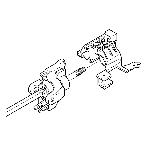
- Remove the tilt head from the steering shaft.
Caution: Refer to SIR Caution in the Preface section.

Installation Procedure
- Install the tilt head onto the steering shaft.
- Install the tilt head housing and steering shaft as an assembly. Refer to Lower Bearing and Steering Column Jacket Replacement .
- Slide the turn signal switch housing onto the steering column shaft assembly.
- Install the turn signal and multifunction switch assembly only. Refer to Turn Signal Multifunction Switch Replacement .
- Install the turn signal cancel cam assembly. Refer to Turn Signal Cancel Cam and Upper Bearing Thrust Washer .
- Enable the SIR system. Refer to SIR Disabling and Enabling in SIR.

Important: The switch mounting bracket must be pressed firmly against the steering column tilt head.
Steering Column Tilt Head Housing Replacement Standard
Tools Required
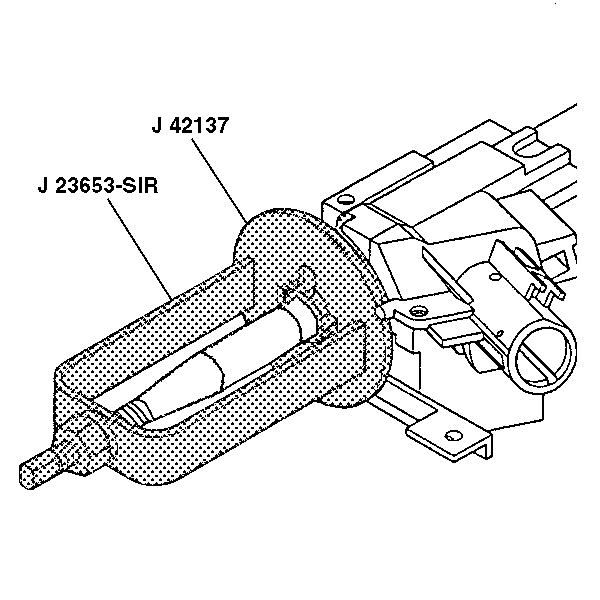
| • | J 23653-SIR Steering Column Lock Plate Compressor |
| • | J 42137 Cam Orientation Plate Adapter |
Removal Procedure
- Disable the SIR system. Refer to SIR Disabling and Enabling in SIR.
- Remove the turn signal cancel cam and upper bearing thrust washer. Refer to Turn Signal Cancel Cam and Upper Bearing Thrust Washer .
- Remove the turn signal and multifunction switch assembly only. Refer to Turn Signal Multifunction Switch Replacement .
- Slide the turn signal switch housing off of the steering column shaft assembly.
- Remove the SIR coil. Refer to Inflatable Restraint Steering Wheel Module Coil Replacement in SIR.
- Compress the cam orientation plate using J 23653-SIR and J 42137 .
- Remove the bearing retainer using J 23653-SIR and J 42137 from the steering column shaft assembly.
- Remove J 23653-SIR and J 42137 from the steering column shaft assembly.
- Discard the bearing retainer.
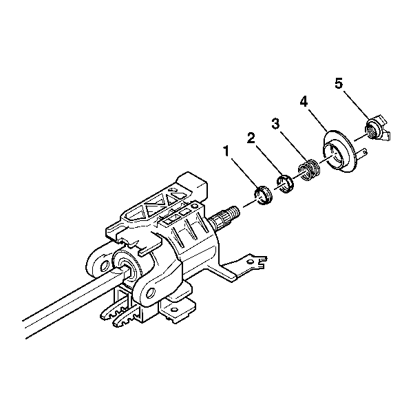
- Remove the following parts from the steering column shaft assembly:
Caution: Refer to SIR Caution in the Preface section.


Important: Let the SIR coil hang freely after removal.

| 10.1. | The cam orientation plate (5) |
| 10.2. | The turn signal cancel cam assembly (4) |
| 10.3. | The upper bearing spring (3) |
| 10.4. | The upper bearing inner race seat (2) |
| 10.5. | The inner race (1) |
| 10.6. | Remove the tilt head housing and steering shaft as an assembly. Refer to Lower Bearing and Steering Column Jacket Replacement . |
| 10.7. | Remove the tilt head from the steering shaft. |
Installation Procedure
- Install the tilt head onto the steering shaft.
- Install the tilt head housing and steering shaft as an assembly. Refer to Lower Bearing and Steering Column Jacket Replacement .
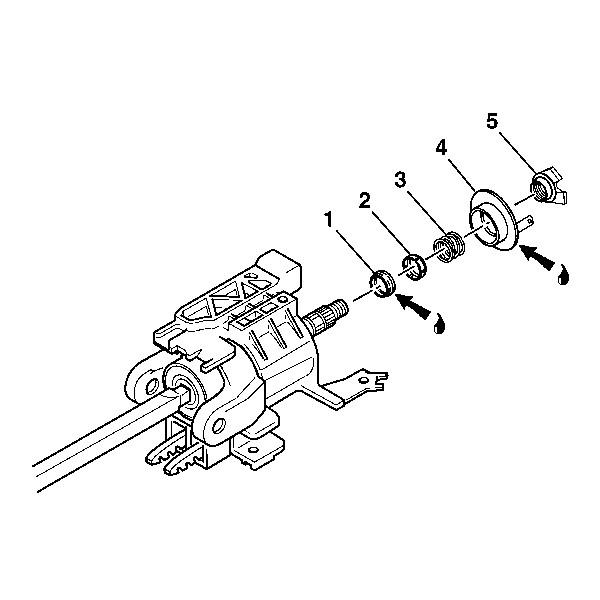
- Lubricate the lower brass surface of the turn signal cancel cam assembly with GM P/N 12377900 (Canadian P/N 10953529).
- Install the following parts onto the steering column shaft assembly:
- Install the new bearing retainer onto the steering column shaft assembly.
- Compress the cam orientation plate using J 23653-SIR and J 42137 .
- Remove J 23653-SIR from the steering column shaft assembly.
- Install the SIR coil. Refer to Inflatable Restraint Steering Wheel Module Coil Replacement in SIR.
- Slide the turn signal switch housing onto the steering column shaft assembly.
- Install the turn signal and multifunction switch assembly only. Refer to Turn Signal Multifunction Switch Replacement .
- Install the turn signal cancel cam and upper bearing thrust. Refer to Turn Signal Cancel Cam and Upper Bearing Thrust Washer .
- Enable the SIR system. Refer to SIR Disabling and Enabling in SIR.

Lubricate the inner race with GM P/N 12345718 (Canadian P/N 10953516)
| 4.1. | The inner race (1) |
| 4.2. | The upper bearing inner race seat (2) |
| 4.3. | The upper bearing spring (3) |
| 4.4. | The turn signal cancel cam assembly (4) |
| 4.5. | The cam orientation plate (5) |

Firmly seat the bearing retainer into the groove on the steering column shaft assembly.

Important: The switch mounting bracket must be pressed firmly against the steering column tilt head.
