For 1990-2009 cars only
Removal Procedure
- Disconnect the negative battery cable. Refer to Battery Negative Cable Disconnection and Connection in Engine Electrical.
- Disable the SIR system. Refer to SIR Disabling and Enabling in SIR.
- Remove the instrument panel (I/P) cluster trim bezel. Refer to Instrument Panel Cluster Trim Plate Bezel Replacement in Instrument Panel, Gages, and Console.
- Remove the driver side knee bolster and deflector. Refer to Knee Bolster Replacement in Instrument Panel, Gages, and Console.
- Remove the left and right I/P end trim panels.
- Remove the park brake release lever from the I/P. Refer to Parking Brake Release Handle Assembly Replacement in Park Brake.
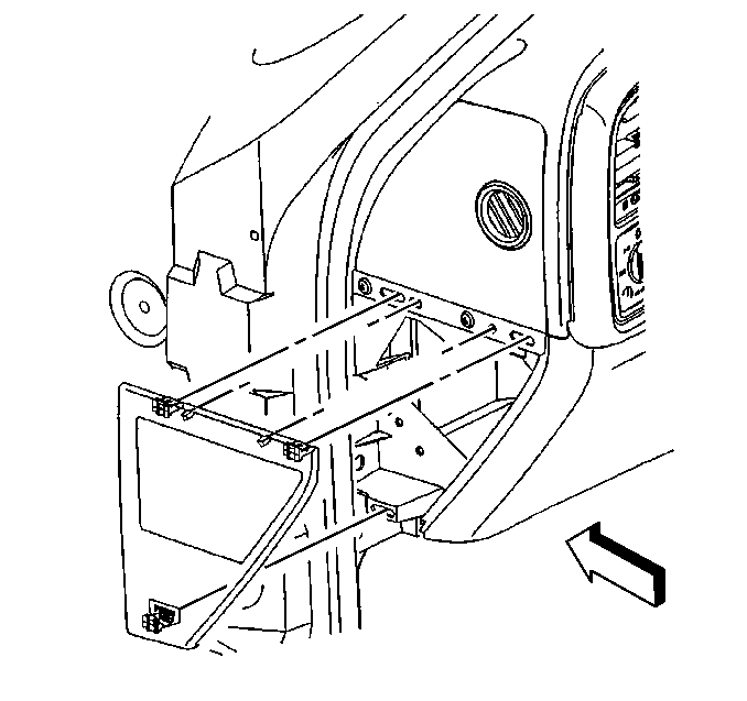
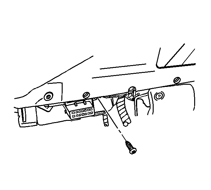
- Remove the data link connector fastener and position aside.
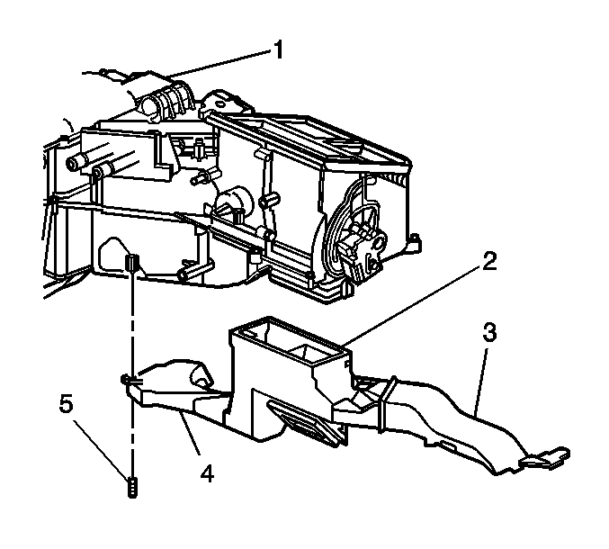
- Remove the left (3) and right (4) air duct.
- Remove the I/P assist handle. Refer to Instrument Panel Assist Handle Replacement in Instrument Panel, Gages, and Console.
- Remove the upper intermediate steering shaft to lower shaft retaining bolt. Refer to Upper Intermediate Steering Shaft Replacement in Steering Wheel and Column.
- Disconnect and reposition the left I/P wiring junction block.
- Remove the windshield garnish moldings. Refer to Windshield Pillar Garnish Molding Replacement in Interior Trim.
- Remove the I/P upper trim panel retaining screws.
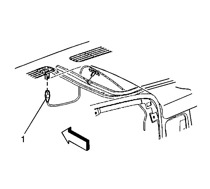
- Lift the trim panel up to disconnect the electrical connector (1) to the ambient light sensor on the underside of the trim panel.
- Remove the trim panel from the vehicle.
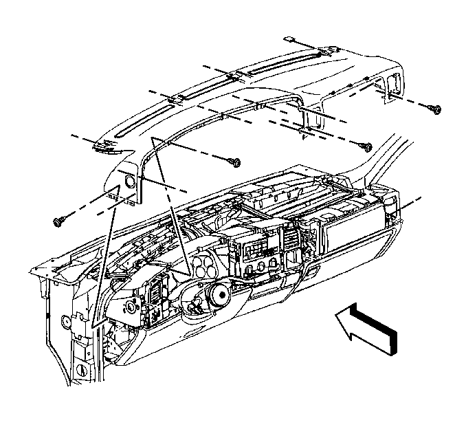
- Remove the I/P upper carrier top bolts.
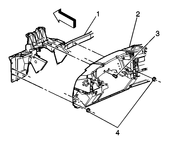
- Remove the I/P center support bracket bezel (1).
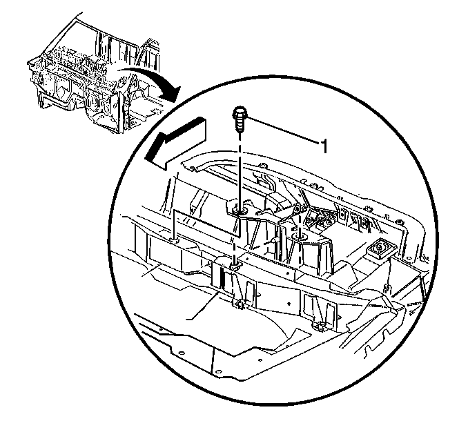
- Remove the I/P center support bracket bolt.
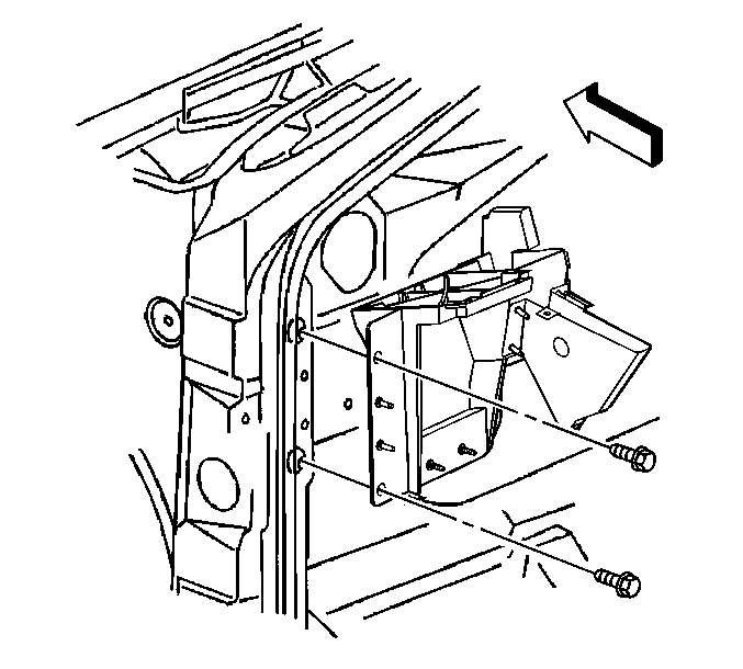
- Remove the I/P carrier retaining bolts. The left side is shown, the right side is similar.
- Remove the left side door sill plate and cowl trim. Refer to Front Side Door Sill Plate Replacement in Interior Trim.
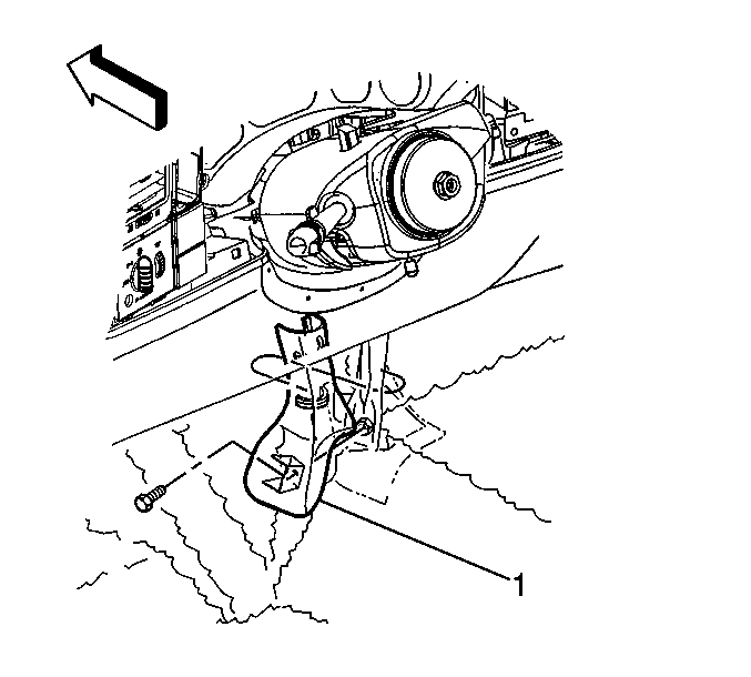
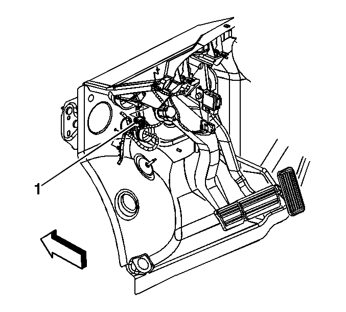
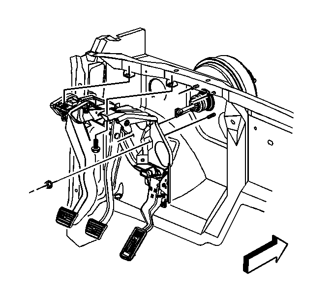
- Disconnect the clutch pedal engine start switch electrical connector (1).
- Push the clutch pedal in and squeeze the pushrod bushing tabs in, in order to release the pushrod bushing from the clutch pedal.
- Remove the pushrod from the pedal.
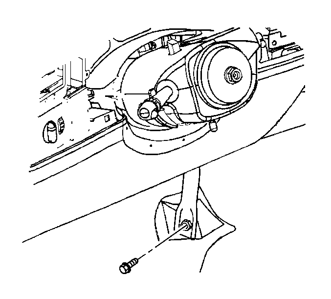
- Remove the clutch master cylinder clip from the brake pressure module valve pipe.
- Rotate the clutch master cylinder 45 degrees clockwise to the unlocked position.
- Pull the clutch master cylinder out until the pushrod socket is not touching the clutch pedal.
- Remove the clutch pedal to clutch pedal bracket bolt .
- Remove the clutch pedal to brake module bolts.
- Remove the I/P carrier bolts. The left side is shown, the right side is similar.
- Allow the instrument panel carrier to move rearward enough to gain access for the clutch pedal assembly removal.
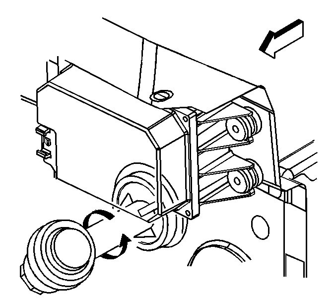
- Remove the clutch pedal sub-assembly.
Caution: Refer to Battery Disconnect Caution in the Preface section.
Important: Complete removal of the clutch master cylinder is not required.
Installation Procedure
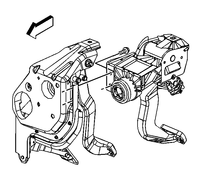
- Install the clutch pedal sub-assembly.
- Install the instrument panel carrier and the right and left bolts. The left side is shown, the right side is similar.
- Install the clutch pedal to brake module bolts.
- Install the clutch pedal to clutch pedal bracket bolt.
- Push the clutch master cylinder in until the pushrod socket is touching the clutch pedal.
- Push in and rotate the clutch master cylinder 45 degrees counterclockwise to the locked position.
- Install the clutch master cylinder clip to the brake pressure module valve pipe.
- Apply light pressure to the clutch pedal to couple the pushrod socket to the clutch pedal.
- Connect the clutch pedal engine start switch electrical connector (1).
- Pump the clutch pedal 3 times prior to starting the vehicle to ensure connection is complete.
- Install the I/P carrier top bolts.
- Install the left side cowl trim and sill plate. Refer to Front Side Door Sill Plate Replacement in Interior Trim.
- Install the I/P center support bracket bolt.
- Install the I/P center support bracket bezel (1).
- Install the I/P assembly retaining bolts (3) and nuts (4). Ensure the wire harness is routed to all of the openings.
- Install the harness hold down retainers to the I/P assembly.
- Connect the electrical connector (1) to the ambient light sensor on the underside of the trim panel.
- Install the trim panel to the I/P assembly.
- Install the trim panel retaining screws.
- Install the windshield pillar garnish moldings. Refer to Windshield Pillar Garnish Molding Replacement in Interior Trim.
- Install the left side I/P junction block.
- Install the upper intermediate steering shaft to lower shaft retaining bolt. Refer to Upper Intermediate Steering Shaft Replacement in Steering Wheel and Column.
- Install the I/P assist handle. Refer to Instrument Panel Assist Handle Replacement in Instrument Panel, Gages, and Console.
- Install the left (3) and right (4) air duct.
- Install the data link connector.
- Install the park brake release handle. Refer to Parking Brake Release Handle Assembly Replacement in Park Brake.
- Install the I/P end trim panels.
- Install the driver side knee bolster and deflector. Refer to Knee Bolster Replacement in Instrument Panel, Gages, and Console.
- Enable the SIR system. Refer to SIR Disabling and Enabling in SIR.
- Connect the negative battery cable. Refer to Battery Negative Cable Disconnection and Connection in Engine Electrical.
Notice: Refer to Fastener Notice in the Preface section.
Tighten
Tighten the bolts to 50 N·m (37 lb ft).
Tighten
Tighten the bolts to 50 N·m (37 lb ft).
Tighten
Tighten the bolt to 36 N·m (27 lb ft).
Tighten
Tighten the bolts to 50 N·m (37 lb ft).
Tighten
Tighten the bolt to 25 N·m (18 lb ft).
Tighten
Tighten the retaining bolts and nuts to 9 N·m (80 lb in).
Tighten
Tighten the screws to 2 N·m (18 lb in).
