GM Service Manual Online
For 1990-2009 cars only
Figure 1:

Module Power, Ground, Serial Data, and MIL
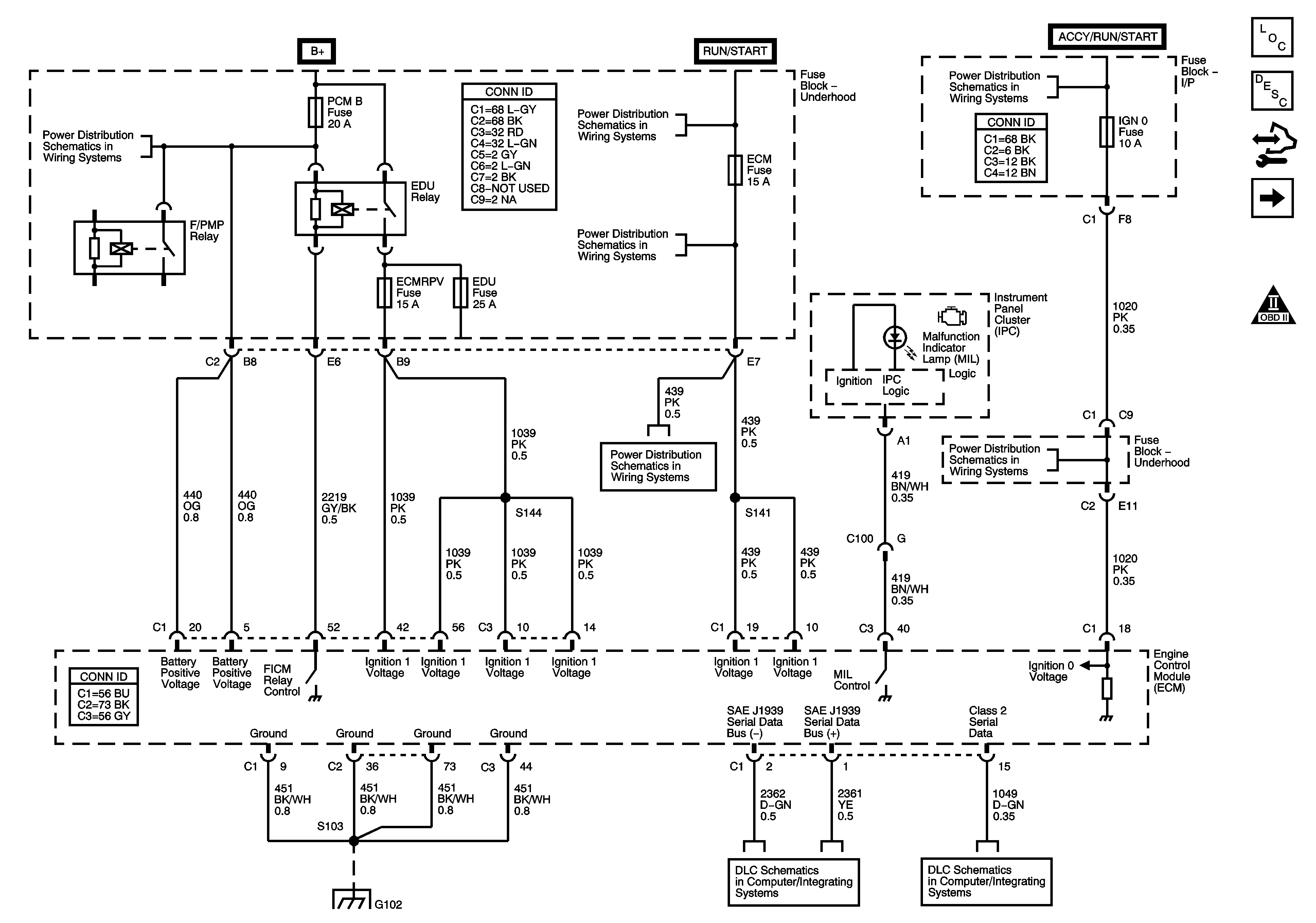

Object Number: 1552021  Size: FS
Master Electrical Component List
Engine Control Module Description
Control Module References
Engine Data Sensors - 5-Volt and Low Reference
Engine Controls Schematic Icons
B+ Bar Bus
Ignition Switch - ACC/RUN and RUN/START Bus Bars and IGN B Fuse
ECM-I, EHPS-I, FUEL HT, and HCM-I Fuses
Ignition Switch - START, RUN, and ACC/RUN/START Bus Bars and IGN A and CRANK Fuses
ECM-I, EHPS-I, FUEL HT, and HCM-I Fuses
IGN 0, RR WPR, SEO ACCY, TBC ACCY, TBC IGN 0, and WS WPR Fuses
G102, G103, G108 and G109 - Diesel
Controller Area Network (CAN) - Diesel
Power, Ground, DLC and Splice Pack SP 205
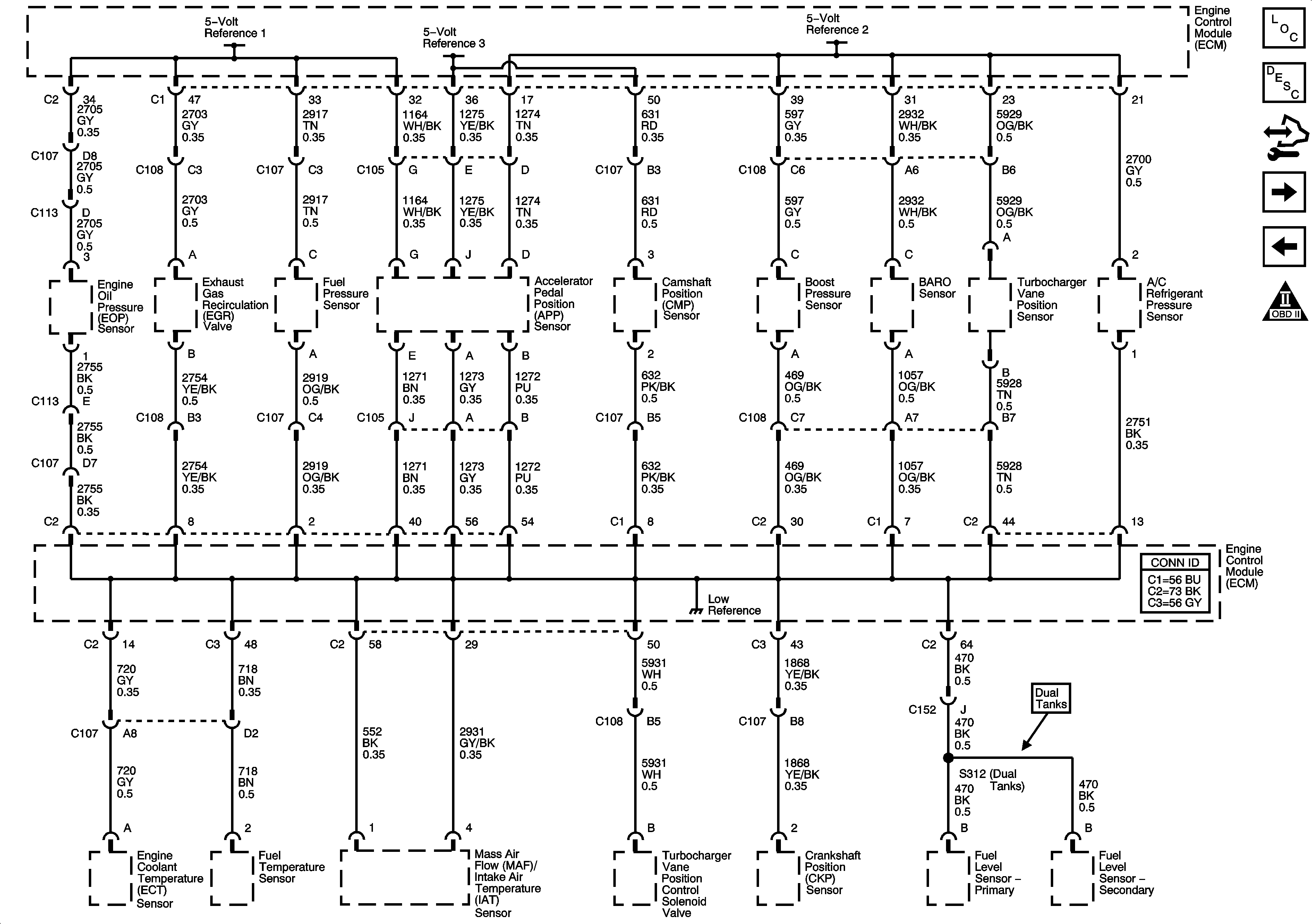
Figure 2:

Engine Data Sensors - 5-Volt and Low Reference


Object Number: 1552023  Size: FS
Master Electrical Component List
Engine Control Module Description
Control Module References
Engine Data Sensors Pressure, Temperature, MAF, and VSS
Module Power, Ground, Serial Data, and MIL
Engine Controls Schematic Icons
Figure 3:

Engine Data Sensors - Pressure, Temperature, MAF, and VSS
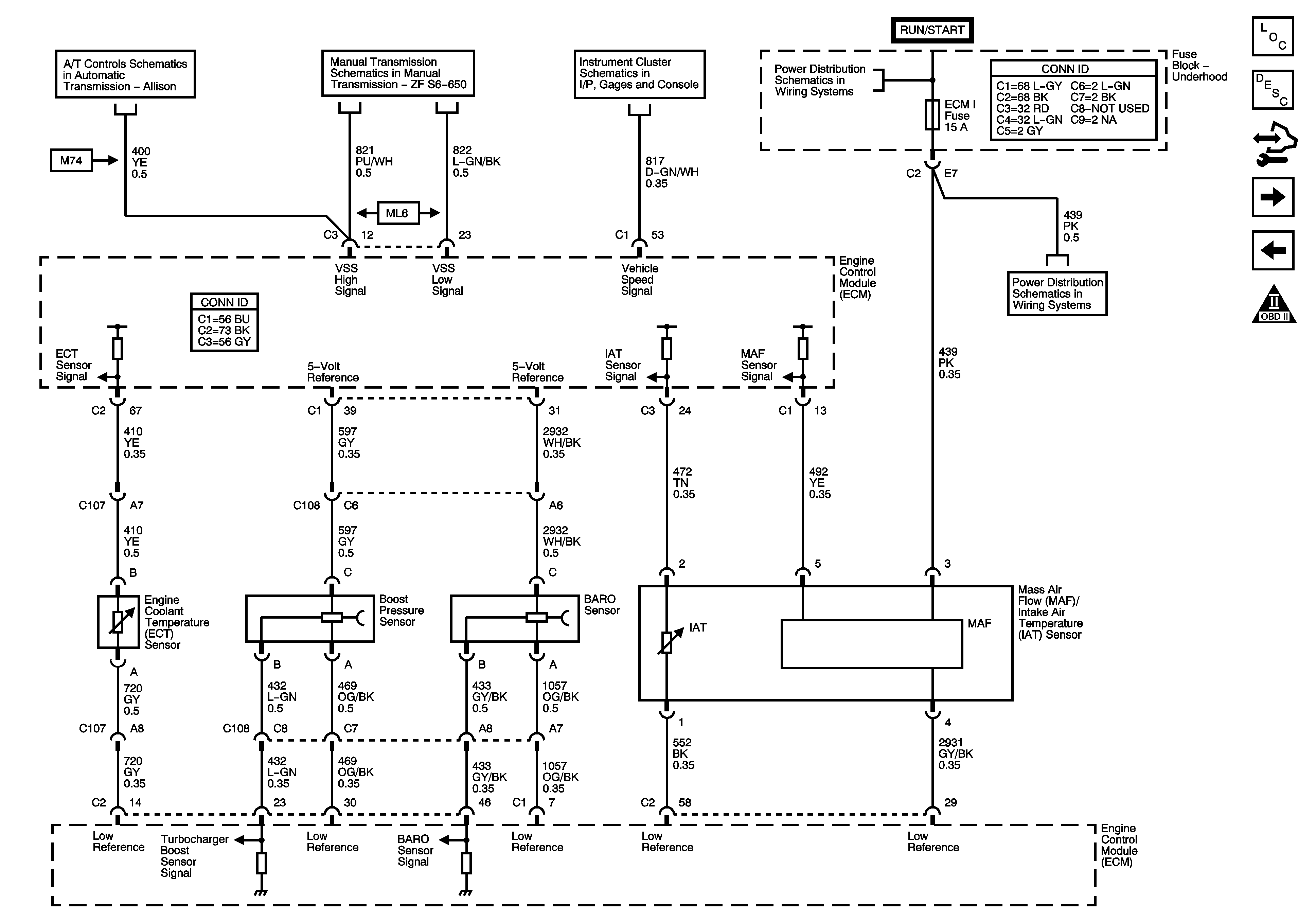

Object Number: 1552025  Size: FS
Master Electrical Component List
Air Intake System Description
Control Module References
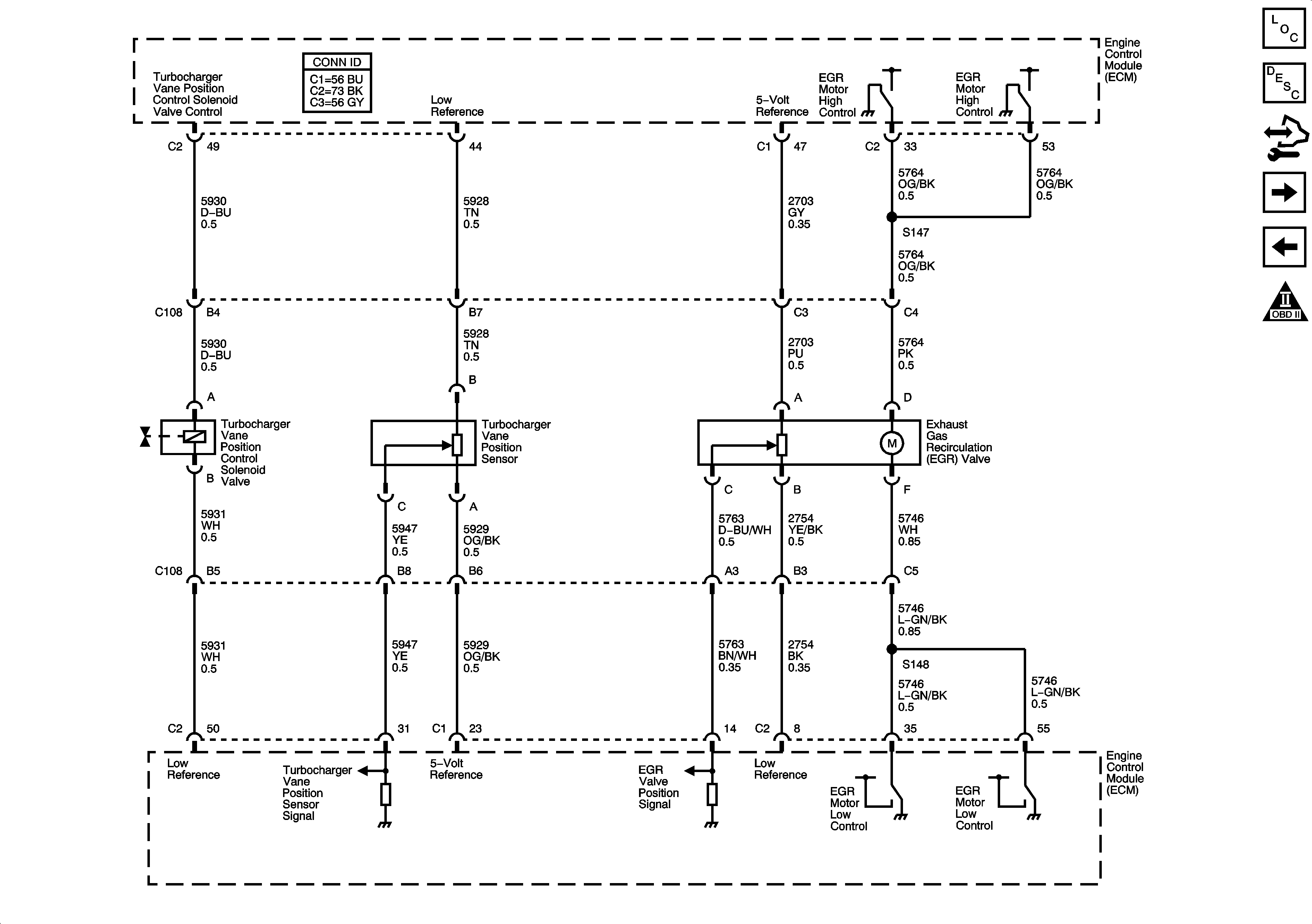
Engine Data Sensors - EGR and Turbocharger Controls
Engine Data Sensors - 5-Volt and Low Reference
Engine Controls Schematic Icons
Speed Sensors and PNP Switches
Manual Transmission ZF S6-650
Gages, Vehicle Speed Signal, Engine Oil Pressure, and Fuel Level Sensors
Ignition Switch - ACC/RUN and RUN/START Bus Bars and IGN B Fuse
ECM-I, EHPS-I, FUEL HT, and HCM-I Fuses
Figure 4:

Engine Data Sensors - EGR and Turbocharger Controls


Object Number: 1552026  Size: FS
Master Electrical Component List
Exhaust Gas Recirculation (EGR) System Description
Control Module References
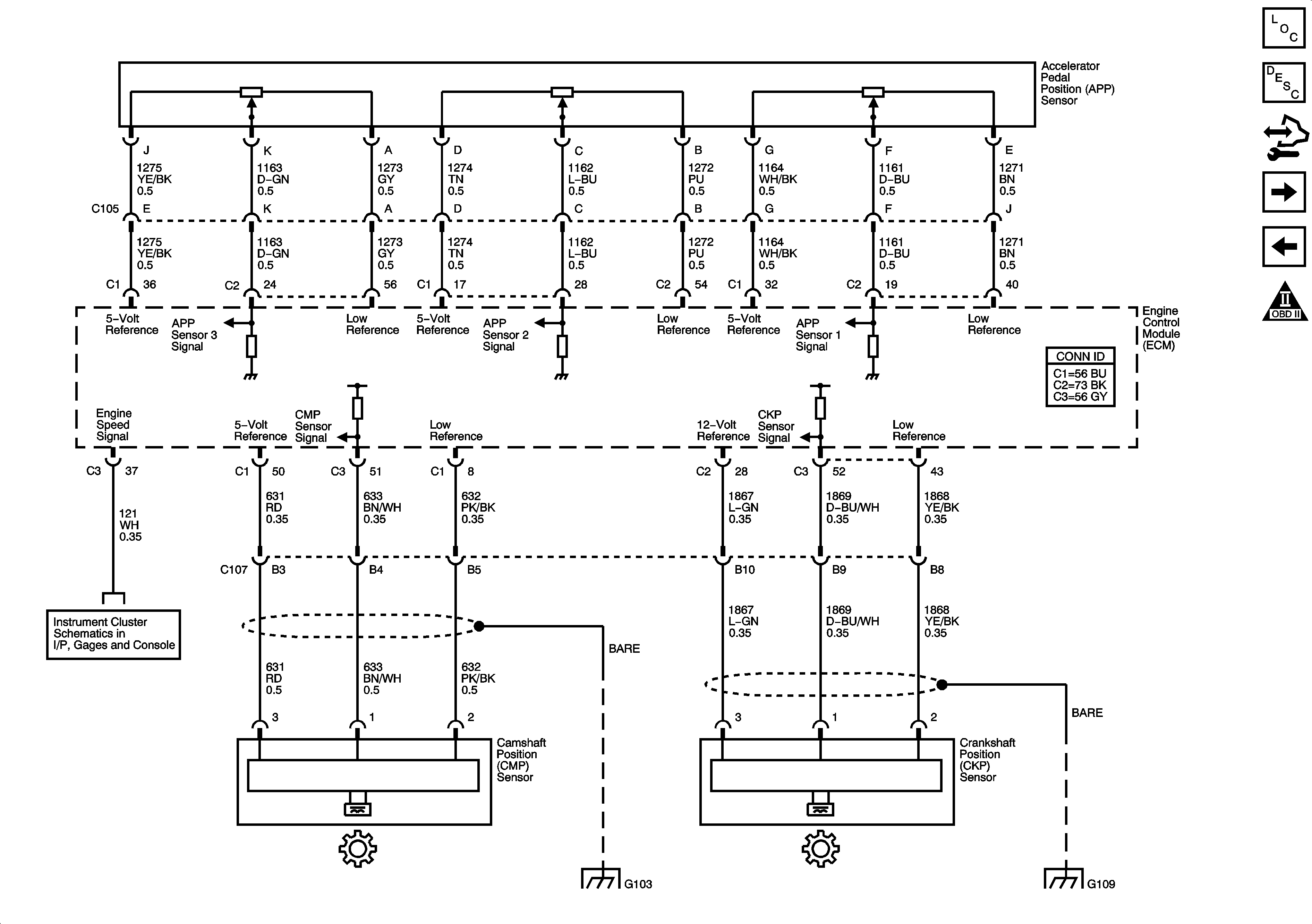
Engine Data Sensors - Pedal Position and Injection Timing
Engine Data Sensors Pressure, Temperature, MAF, and VSS
Engine Controls Schematic Icons
Figure 5:

Engine Data Sensors - Pedal Position and Injection Timing


Object Number: 1552027  Size: FS
Master Electrical Component List
Accelerator Pedal Position System Description
Control Module References
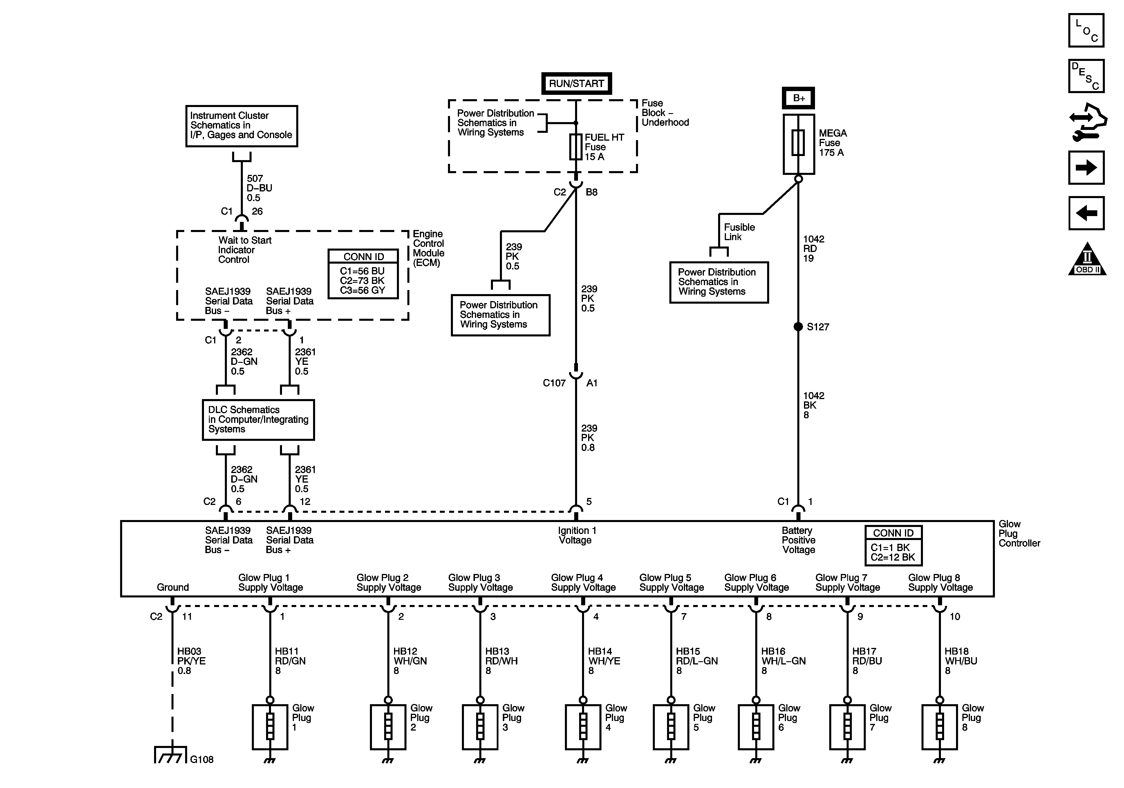
Engine Data Sensors - Glow Plug Controls
Engine Data Sensors - EGR and Turbocharger Controls
Engine Controls Schematic Icons
Gages, Vehicle Speed Signal, Engine Oil Pressure, and Fuel Level Sensors
G102, G103, G108 and G109 - Diesel
Figure 6:

Engine Data Sensors - Glow Plug Controls


Object Number: 1552028  Size: FS
Master Electrical Component List
Glow Plug System Description
Control Module References
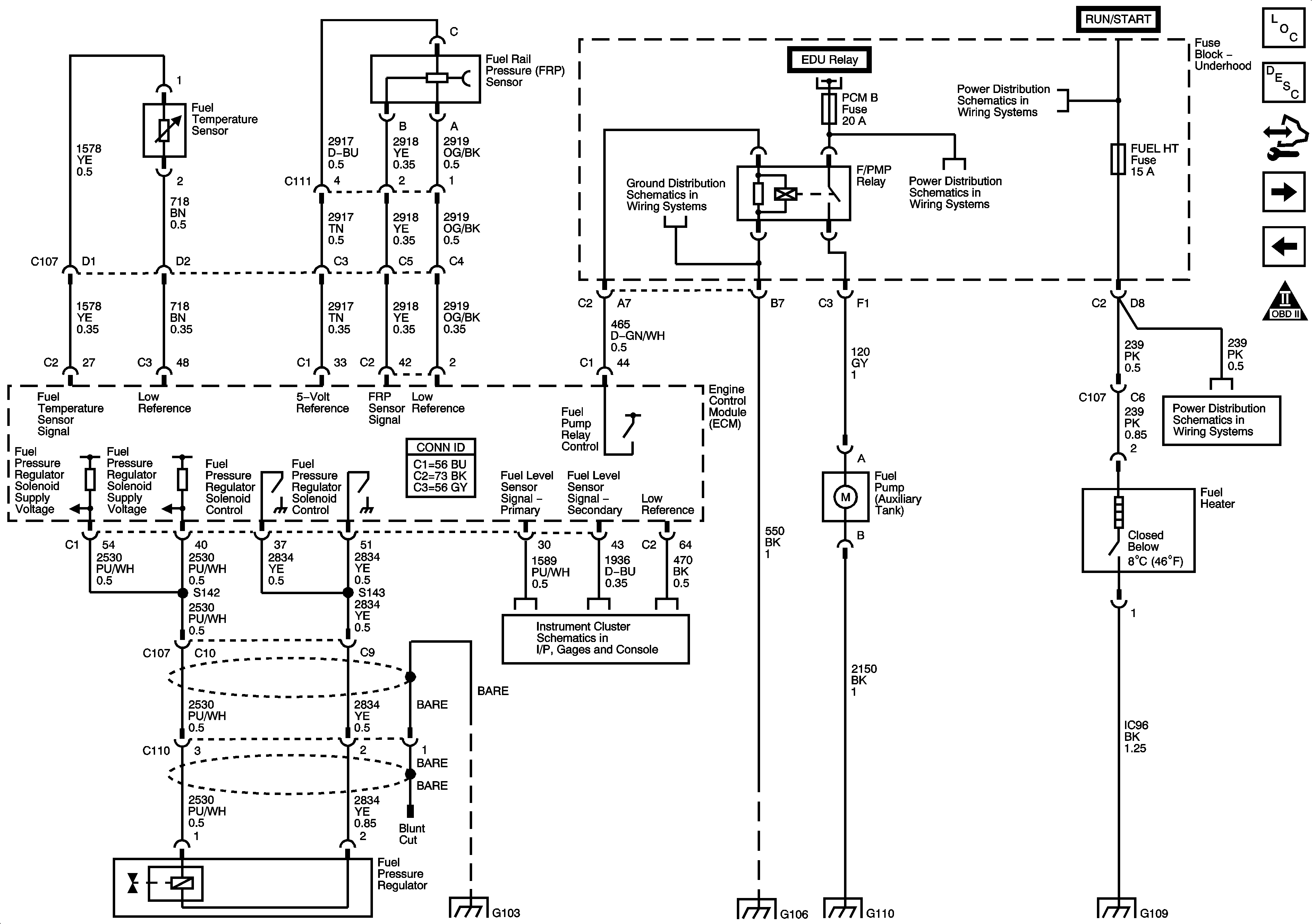
Fuel Controls - Fuel Pump, Temperature, and Pressure Controls
Engine Data Sensors - Pedal Position and Injection Timing
Engine Controls Schematic Icons
Indicators, Water in Fuel Sensor, Engine Oil Level Switch and Washer Fluid Level Sensor
Ignition Switch - ACC/RUN and RUN/START Bus Bars and IGN B Fuse
Controller Area Network (CAN) - Diesel
ECM-I, EHPS-I, FUEL HT, and HCM-I Fuses
Battery Supply - 2 of 2
G102, G103, G108 and G109 - Diesel
Figure 7:

Fuel Controls - Fuel Pump, Temperature, and Pressure Controls


Object Number: 1552029  Size: FS
Master Electrical Component List
Fuel System Description
Control Module References
Fuel Controls - Fuel Injectors
Engine Data Sensors - Glow Plug Controls
Engine Controls Schematic Icons
G102, G103, G108 and G109 - Diesel
Module Power, Ground, Serial Data, and MIL
AUX PWR, AUX PWR 2, DDM, ECC, LBEC 2, LOCKS, PCM B, and PDM Fuses
Ignition Switch - ACC/RUN and RUN/START Bus Bars and IGN B Fuse
ECM-I, EHPS-I, FUEL HT, and HCM-I Fuses
G102, G103, G108 and G109 - Diesel
Gages, Vehicle Speed Signal, Engine Oil Pressure, and Fuel Level Sensors
G102, G103, G108 and G109 - Diesel
G104, G106, G107 and G110
G102, G103, G108 and G109 - Diesel
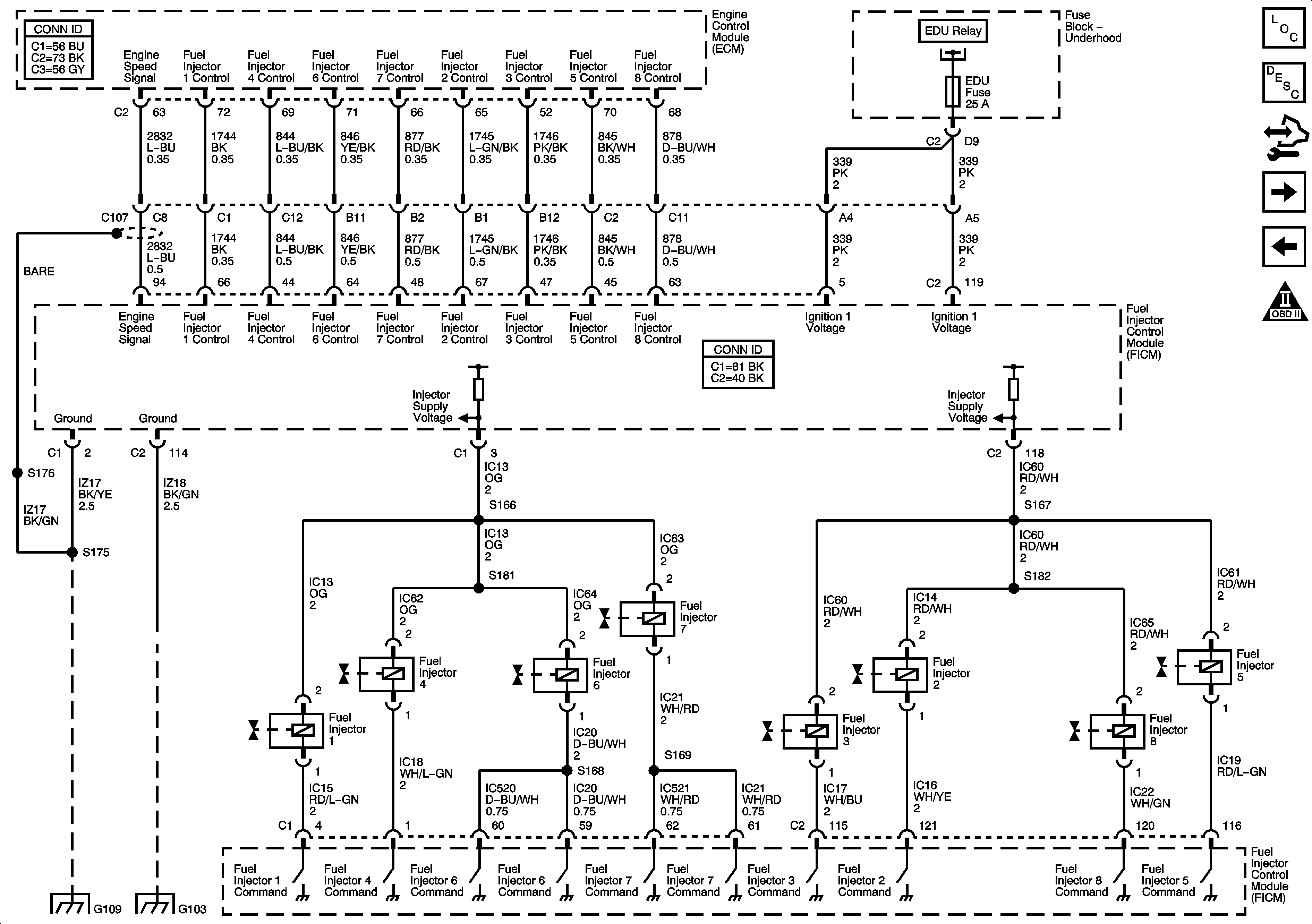
Figure 8:

Fuel Controls - Fuel Injectors


Object Number: 1552030  Size: FS
Master Electrical Component List
Fuel System Description
Control Module References
Controlled/Monitored Subsystem References
Fuel Controls - Fuel Pump, Temperature, and Pressure Controls
Engine Controls Schematic Icons
Module Power, Ground, Serial Data, and MIL
G102, G103, G108 and G109 - Diesel
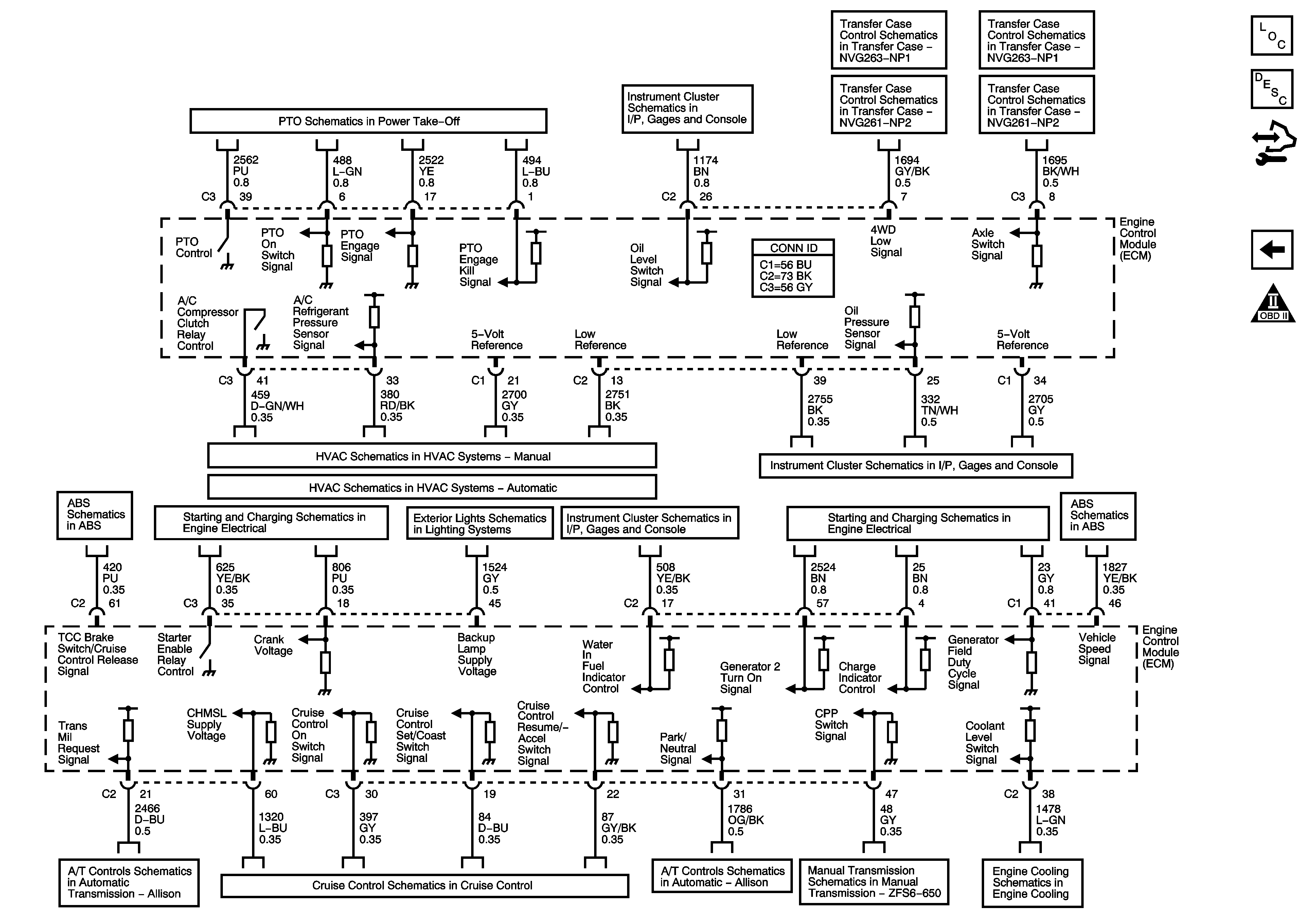
Figure 9:

Controlled/Monitored Subsystem References


Object Number: 1552031  Size: FS
Master Electrical Component List
Engine Control Module Description
Control Module References
Fuel Controls - Fuel Injectors
Engine Controls Schematic Icons
Power Takeoff
Indicators, Water in Fuel Sensor, Engine Oil Level Switch and Washer Fluid Level Sensor
Power, Ground, Serial Data and Transfer Case Encoder Motor
Transfer Case Control Schematics NP2
Power, Ground, Serial Data and Transfer Case Encoder Motor
Transfer Case Control Schematics NP2
A/C Compressor Controls
Gages, Vehicle Speed Signal, Engine Oil Pressure, and Fuel Level Sensors
Power, Ground, Serial Data, Indicator and Stop Lamp Switch - Over 8600 GVW or Rear Drum Brakes
Starting - Diesel
Backup Lamps
Indicators, Water in Fuel Sensor, Engine Oil Level Switch and Washer Fluid Level Sensor
Charging - Diesel
Power, Ground, Serial Data, Indicator and Stop Lamp Switch - Over 8600 GVW or Rear Drum Brakes
MIL Control, Serial Data, Torque Signal and Tow/Haul Switch
Diesel
Speed Sensors and PNP Switches
Manual Transmission ZF S6-650
8.1L and Diesel