For 1990-2009 cars only
Removal Procedure
- Drain the cooling system. Refer to Generator Control Module Cooling System Draining and Filling .
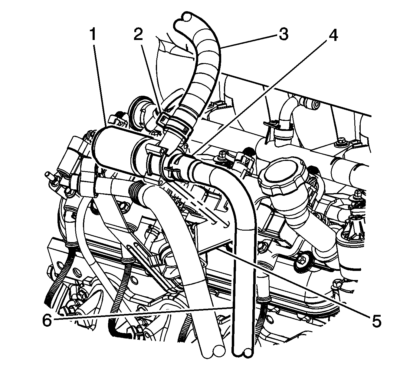
- Reposition the front heater inlet hose clamp (4) from the auxiliary water pump (1).
- Remove the front heater inlet hose (6) from the auxiliary water pump (1).
- Reposition the rear heater inlet hose clamp (2) from the auxiliary water pump (1).
- Remove the rear heater inlet hose (3) from the auxiliary water pump (1).
- Remove the heater outlet hose from the clip.
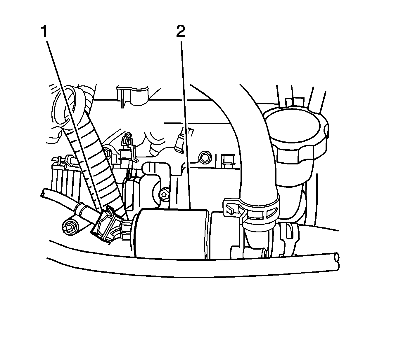
- Disconnect the electrical connector (1) from the auxiliary water pump (2).
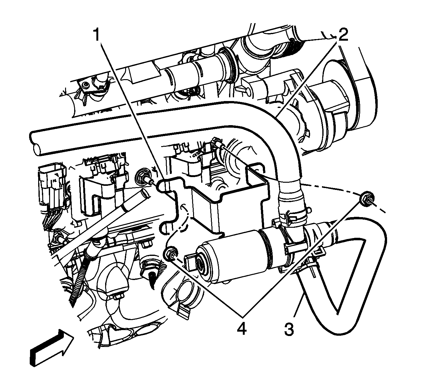
- Remove the nuts (4) from the auxiliary water pump bracket (1).
- Remove the auxiliary water pump (1) from the vehicle.
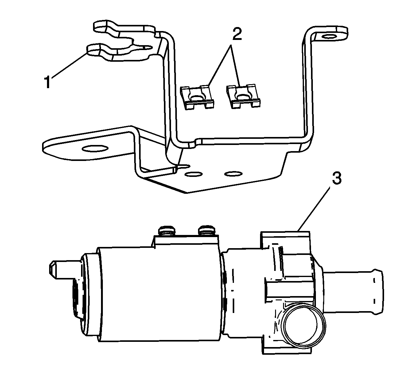
- Remove the clips (2) from the auxiliary water pump bracket (1).
- Remove the auxiliary water pump (3) from the auxiliary water pump bracket (1).


Installation Procedure
- Install the auxiliary water pump (3) to the auxiliary water pump bracket (1).
- Install the clips (2) to the auxiliary water pump bracket (1).
- Install the auxiliary water pump (1) to the vehicle.
- Install the nuts (4) to the auxiliary water pump bracket (1).
- Connect the electrical connector (1) to the auxiliary water pump (2).
- Install the heater outlet hose to the clip.
- Install the rear heater inlet hose (3) to the auxiliary water pump (1).
- Position the rear heater inlet hose clamp (2) to the auxiliary water pump (1).
- Install the front heater inlet hose (6) to the auxiliary water pump (1).
- Position the front heater inlet hose clamp (4) to the auxiliary water pump (1).
- Fill the cooling system. Refer to Generator Control Module Cooling System Draining and Filling .


Notice: Refer to Fastener Notice in the Preface section.
Tighten
Tighten the nuts to 9 N·m (80 lb in).


