Generator Bracket Replacement 6.6L Engine
Removal Procedure
- Disconnect the negative battery cable. Refer to Battery Negative Cable Disconnection and Connection .
- Remove the air cleaner assembly. Refer to Air Cleaner Assembly Replacement in Engine Controls - 6.6L.
- Remove the drive belt. Refer to Drive Belt Replacement in Engine Mechanical-6.6L.
- Remove the upper fan shroud. Refer to Engine Coolant Fan Upper Shroud Replacement in Engine Cooling.
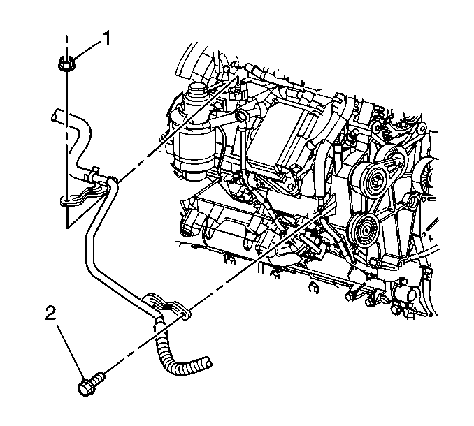
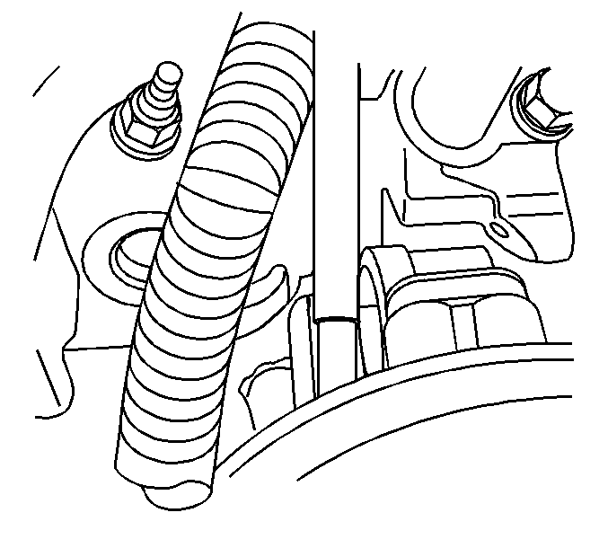
- Remove the outlet heater hose bracket bolt (2).
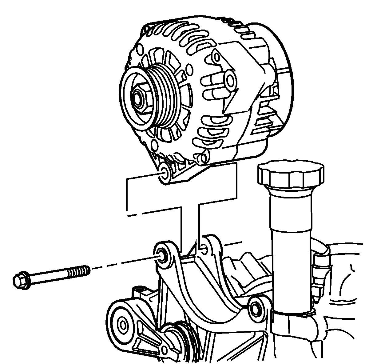
- Remove the generator bolts and reposition the generator aside. The electrical connections can remain attached to the generator.
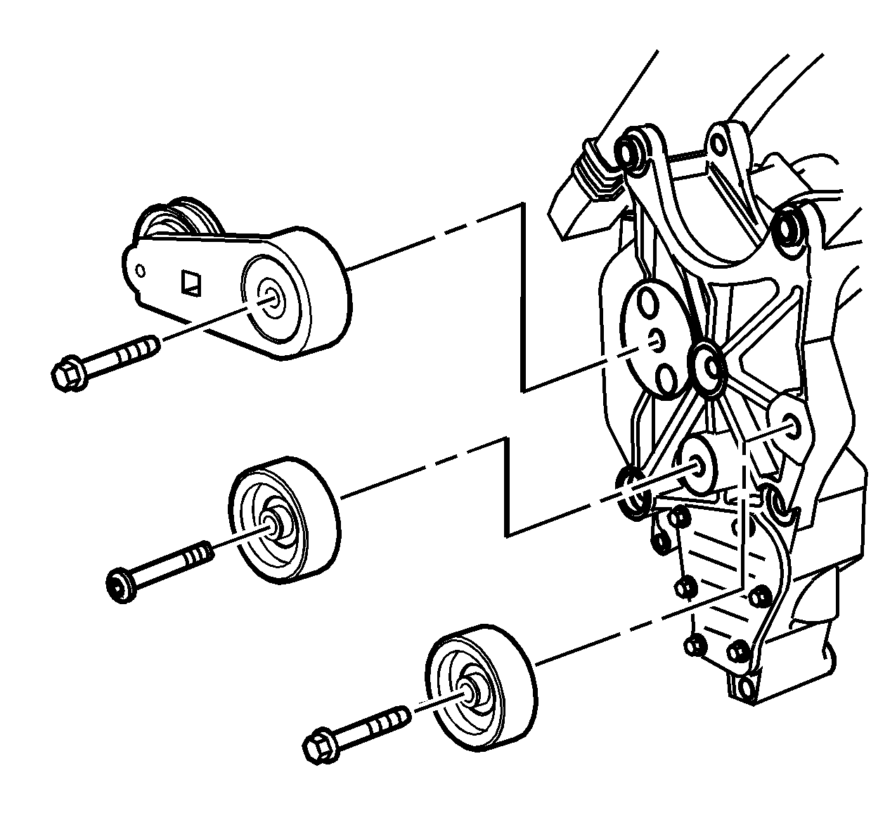
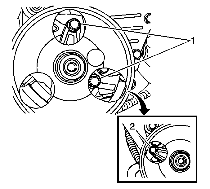
- Remove the right idler pulley bolt and pulley.
- Remove the left idler pulley bolt and pulley.
- Remove the drive belt tensioner bolt and tensioner.
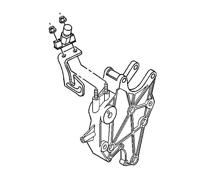
- Remove the fuel bleed valve nuts and valve.
- Reposition the oil separator hose clamp at the side of the generator bracket.
- Remove the oil separator hose from the pipe.
- If equipped, remove the vacuum line from the exhaust gas recirculation (EGR) valve vacuum pump.
- If equipped, remove the EGR vacuum pump bolts. Reposition the vacuum pump.
- Reposition the oil separator hose clamp at the bottom of the generator bracket.
- Remove the oil separator hose from the bracket.
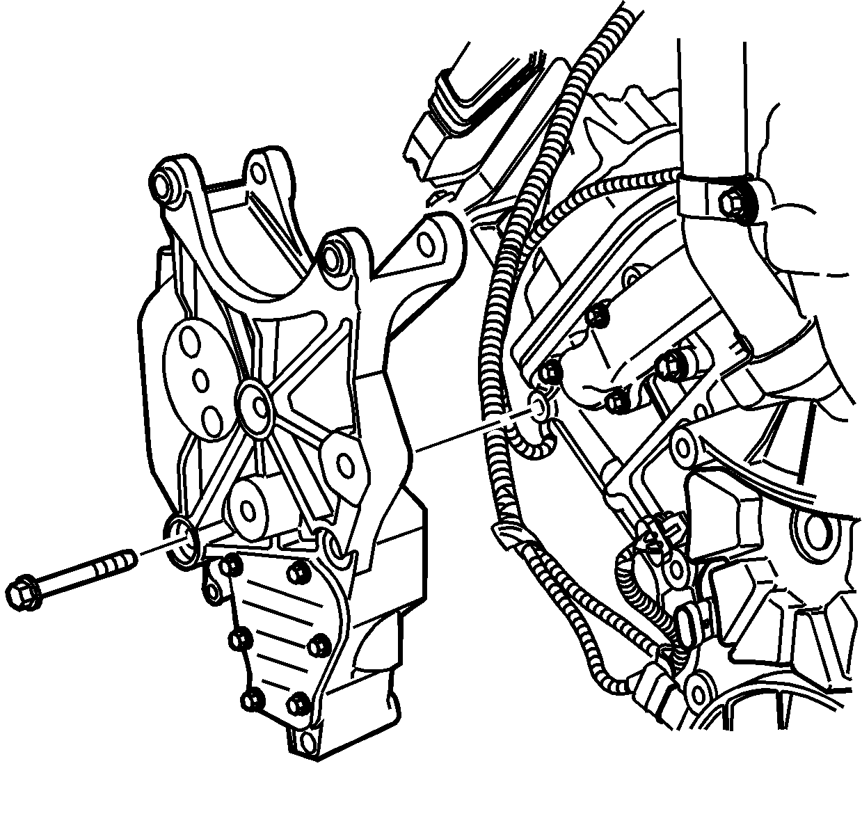
- Remove the generator bracket bolts.
- Remove the generator bracket.
Installation Procedure
- Install the generator bracket.
- Install the generator bracket bolts.
- Install the oil separator hose to the bracket.
- Position the oil separator hose clamp at the bottom of the generator bracket.
- If equipped, position the vacuum pump. Install the EGR vacuum pump bolts.
- If equipped, install the vacuum line to the EGR valve vacuum pump.
- Install the oil separator hose to the pipe.
- Position the oil separator hose clamp at the side of the generator bracket.
- Install the fuel bleed valve and nuts.
- Install the drive belt tensioner and bolt. Align the pin on the tensioner with the hole in the bracket.
- Install the left idler pulley and bolt.
- Install the right idler pulley and bolt.
- Position the generator and install the bolts.
- Install the outlet heater hose bracket bolt (2).
- Install the upper fan shroud. Refer to Engine Coolant Fan Upper Shroud Replacement in Engine Cooling.
- Install the drive belt. Refer to Drive Belt Replacement in Engine Mechanical-6.6L.
- Install the air cleaner assembly. Refer to Air Cleaner Assembly Replacement in Engine Controls - 6.6L.
- Connect the negative battery cable. Refer to Battery Negative Cable Disconnection and Connection .

Notice: Use the correct fastener in the correct location. Replacement fasteners must be the correct part number for that application. Fasteners requiring replacement or fasteners requiring the use of thread locking compound or sealant are identified in the service procedure. Do not use paints, lubricants, or corrosion inhibitors on fasteners or fastener joint surfaces unless specified. These coatings affect fastener torque and joint clamping force and may damage the fastener. Use the correct tightening sequence and specifications when installing fasteners in order to avoid damage to parts and systems.
Tighten
Tighten the bolts to 50 N·m (37 lb ft).

Tighten
Tighten the bolts to 22 N·m (16 lb ft).


Tighten
Tighten the nuts to 25 N·m (18 lb ft).

Tighten
Tighten the bolt to 41 N·m (30 lb ft).
Tighten
Tighten the bolts to 43 N·m (32 lb ft).

Tighten
Tighten the bolts to 50 N·m (37 lb ft).

Tighten
Tighten the bolt to 25 N·m (18 lb ft).
Generator Bracket Replacement 4.3L Engine
Removal Procedure
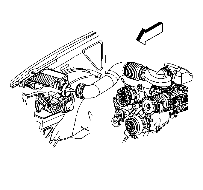
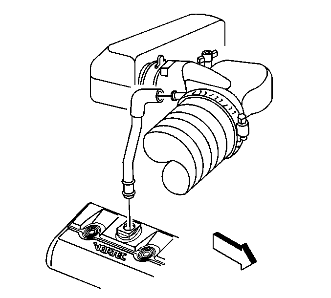
- Loosen the air cleaner outlet duct clamp at the mass air flow/intake air temperature (MAF/IAT) sensor.
- Remove the positive crankcase ventilation (PCV) hose.
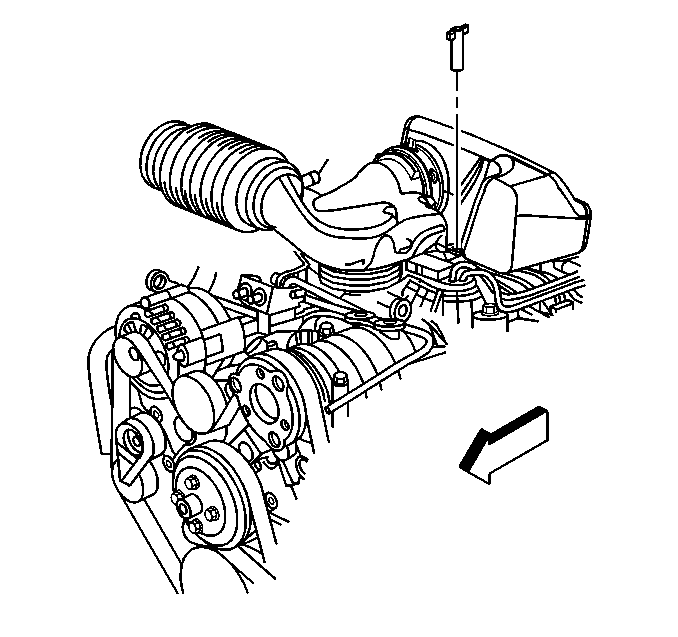
- Remove the air cleaner adapter nut.
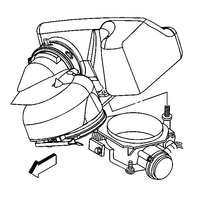
- In order to remove the air cleaner outlet duct, pivot the duct upward until the hinge clip releases from the lip on the throttle body.
- Remove the cooling fan. Refer to Fan Replacement in Engine Cooling.
- Remove the drive belt. Refer to Drive Belt Replacement in Engine Mechanical - 4.3L.
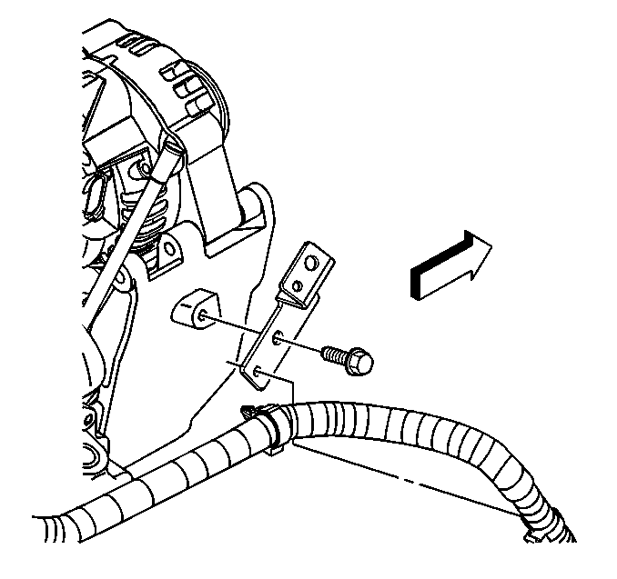
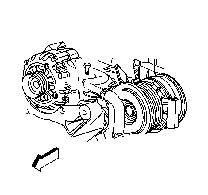
- Remove the wiring harness bracket bolt.
- Remove the heater hose bracket bolt.
- Remove the generator. Refer to Generator Replacement .
- Remove the drive belt tensioner. Refer to Drive Belt Tensioner Replacement in Engine Mechanical - 4.3L.
- Remove the drive belt idler pulley. Refer to Drive Belt Idler Pulley Replacement - Right Side or Drive Belt Idler Pulley Replacement - without Air Conditioning in Engine Mechanical - 4.3L.
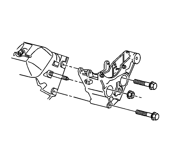
- Remove the generator bracket bolts and nut.
- Remove the generator bracket.
Installation Procedure
- Install the generator bracket.
- Install the generator bracket bolts and nut.
- Install the drive belt idler pulley. Refer to Drive Belt Idler Pulley Replacement - Right Side or Drive Belt Idler Pulley Replacement - without Air Conditioning in Engine Mechanical - 4.3L.
- Install the drive belt tensioner. Refer to Drive Belt Tensioner Replacement in Engine Mechanical - 4.3L.
- Install the generator. Refer to Generator Replacement .
- Install the heater hose bracket bolt.
- Install the wiring harness bracket bolt.
- Install the cooling fan. Refer to Fan Replacement in Engine Cooling.
- Install the drive belt. Refer to Drive Belt Replacement in Engine Mechanical - 4.3L.
- Align the hinge clip with the lip on the throttle body.
- Install the air cleaner adapter nut.
- Install the PCV hose.
- Tighten the air cleaner outlet duct clamp at the MAF/IAT sensor.

Notice: Use the correct fastener in the correct location. Replacement fasteners must be the correct part number for that application. Fasteners requiring replacement or fasteners requiring the use of thread locking compound or sealant are identified in the service procedure. Do not use paints, lubricants, or corrosion inhibitors on fasteners or fastener joint surfaces unless specified. These coatings affect fastener torque and joint clamping force and may damage the fastener. Use the correct tightening sequence and specifications when installing fasteners in order to avoid damage to parts and systems.
Tighten
Tighten the bolts/nut to 41 N·m (30 lb ft).

Tighten
Tighten the bolt to 25 N·m (18 lb ft).

Tighten
Tighten the bolt to 25 N·m (18 lb ft).

In order to install the air cleaner outlet duct, pivot the air cleaner outlet duct downward until the mounting stud is through the hole.


Tighten
Tighten the clamp to 4 N·m (35 lb in).
Generator Bracket Replacement 4.8L, 5.3L, and 6.0L Engines
Removal Procedure
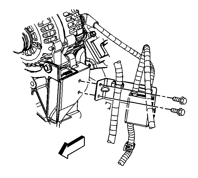
- Remove the battery cable junction block bracket bolts.
- Remove the generator. Refer to Generator Replacement .
- Remove the power steering pump. Refer to Power Steering Pump Replacement .
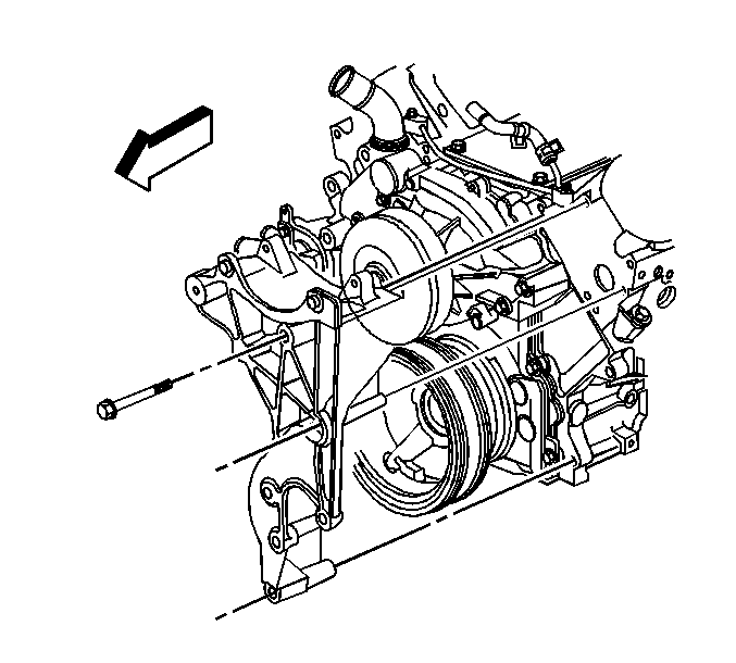
- Remove the generator bracket bolts.
- Remove the generator bracket.
Installation Procedure
- Install the generator bracket.
- Install the generator bracket bolts.
- Install the power steering pump. Refer to Power Steering Pump Replacement .
- Install the generator. Refer to Generator Replacement .
- Install the battery cable junction block bracket bolts.

Notice: Use the correct fastener in the correct location. Replacement fasteners must be the correct part number for that application. Fasteners requiring replacement or fasteners requiring the use of thread locking compound or sealant are identified in the service procedure. Do not use paints, lubricants, or corrosion inhibitors on fasteners or fastener joint surfaces unless specified. These coatings affect fastener torque and joint clamping force and may damage the fastener. Use the correct tightening sequence and specifications when installing fasteners in order to avoid damage to parts and systems.
Tighten
Tighten the bolts to 50 N·m (37 lb ft).

Tighten
Tighten the bolts to 9 N·m (80 lb in).
Generator Bracket Replacement 8.1L Engine
Removal Procedure
- Remove the battery cable junction block bracket bolts.
- Remove the fan and clutch. Refer to Fan Clutch Replacement .
- Remove the drive belt idler pulley. Refer to Drive Belt Idler Pulley Replacement
- Remove the generator. Refer to Generator Replacement .
- Remove the generator bracket bolts and nut.
- Remove the generator bracket stud.
- Remove the generator bracket.
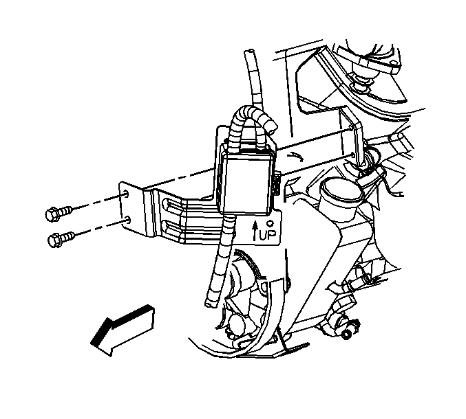
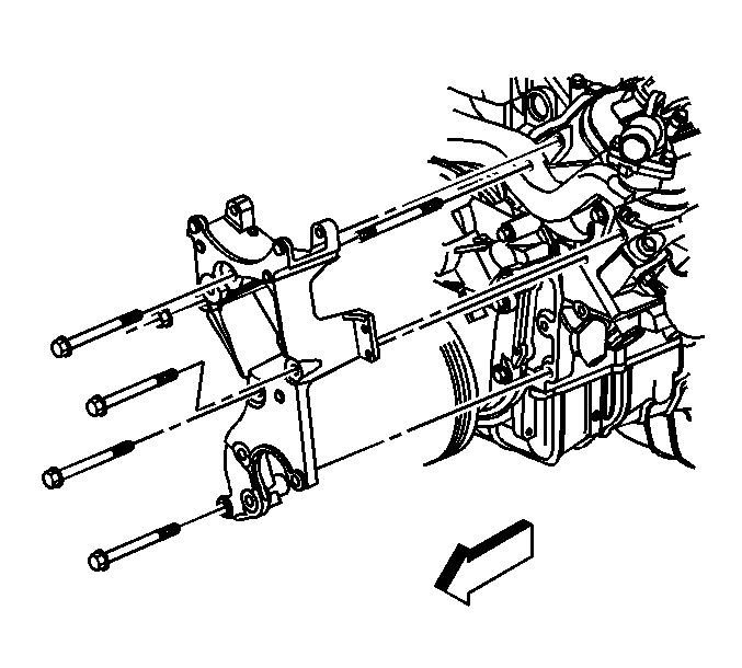
.
Installation Procedure
- Install the generator bracket.
- Install the generator bracket stud.
- Install the generator bracket bolts and nut.
- Install the generator. Refer to Generator Replacement .
- Install the drive belt idler pulley. Refer to Drive Belt Idler Pulley Replacement .
- Install the fan and clutch. Refer to Fan Clutch Replacement .
- Install the battery cable junction block bracket bolts.

Notice: Use the correct fastener in the correct location. Replacement fasteners must be the correct part number for that application. Fasteners requiring replacement or fasteners requiring the use of thread locking compound or sealant are identified in the service procedure. Do not use paints, lubricants, or corrosion inhibitors on fasteners or fastener joint surfaces unless specified. These coatings affect fastener torque and joint clamping force and may damage the fastener. Use the correct tightening sequence and specifications when installing fasteners in order to avoid damage to parts and systems.
Tighten
Tighten the stud to 20 N·m (15 lb ft).
Tighten
Tighten the bolts and nut to 50 N·m (37 lb ft).

Tighten
Tighten the bolts to 9 N·m (80 lb in).
