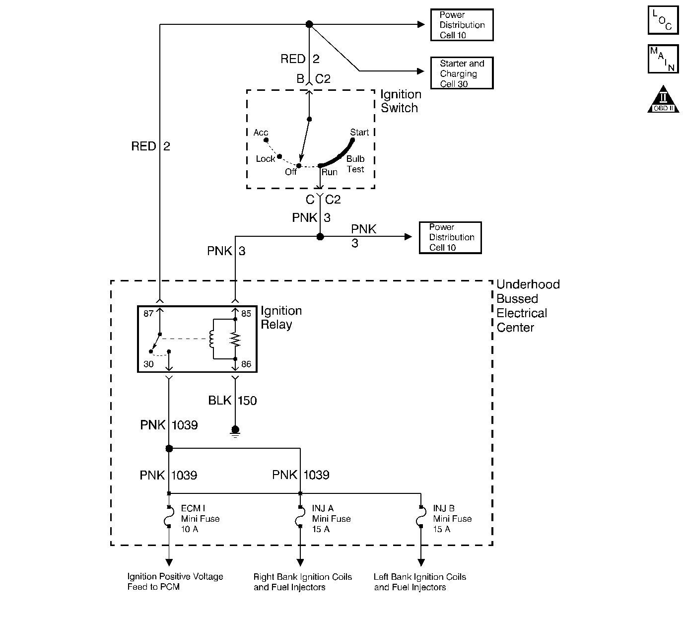
Circuit Description
The IGN relay powers the following components:
| • | Injectors/Ignition coils |
| • | AIR relay |
Diagnostic Aids
The following may cause an intermittent:
| • | Poor connections. Check for adequate terminal tension. Refer to Intermittents and Poor Connections Diagnosis in Wiring Systems. |
| • | Corrosion |
| • | Mis-routed harness. |
| • | Rubbed through wire insulation. |
| • | Broken wire inside the insulation. |
Test Description
The numbers below refer to the step numbers on the diagnostic table.
-
Refer to Thumbnail Schematic for proper relay terminal identification.
-
This step is testing the relay ground circuit. For any test that requires probing the PCM or a component harness connector, use the Connector Test Adapter Kit J 35616 . Using this kit prevents damage to the harness connector terminals. Refer to Using Connector Test Adapters in Wiring Systems.
-
This step isolates the circuit from the IGN relay. All of the circuits at the relay are good if the test lamp illuminates.
-
The open circuit will be between the splice and the IGN relay.
-
Remove the underhood electrical center cover and inspect the circuits that are supplied a voltage by the IGN relay.
Step | Action | Value(s) | Yes | No | ||||||
|---|---|---|---|---|---|---|---|---|---|---|
1 | Did you perform the Powertrain On-Board Diagnostic (OBD) System Check? | -- | ||||||||
Does the test lamp illuminate? | -- | |||||||||
3 |
Does the test lamp illuminate? | -- | ||||||||
Is the resistance less than the specified value? | 0-5ohms | |||||||||
Does the test lamp illuminate? | -- | |||||||||
6 | Inspect for poor terminal contact at the IGN relay underhood electrical center connector. Refer to Intermittents and Poor Connections Diagnosis in Wiring Systems. Did you find and correct the condition? | -- | System OK | |||||||
7 | Replace the IGN relay. Is the action complete? | -- | System OK | -- | ||||||
8 | Repair the open B+ supply to the IGN relay. Refer to Wiring Repairs in Wiring Systems. Is the action complete? | -- | System OK | -- | ||||||
Repair the ignition feed circuit to the IGN relay. Refer to Wiring Repairs in Wiring Systems. Is the action complete? | -- | System OK | -- | |||||||
10 | Replace the underhood electrical center. Refer to Underhood Fuse Block Replacement in Wiring Systems. Is the action complete? | -- | System OK | -- | ||||||
Replace the Underhood Electrical Center. Refer to Underhood Fuse Block Replacement in Wiring Systems. Is the action complete? | -- | System OK | -- |
