- Position the vehicle on a smooth and level surface.
- Use a bubble protractor or inclinometer in order to measure the frame angle.
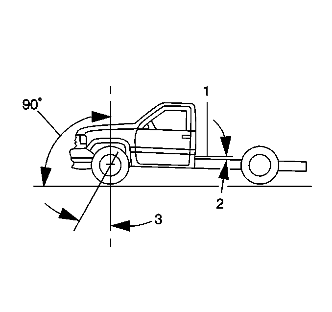
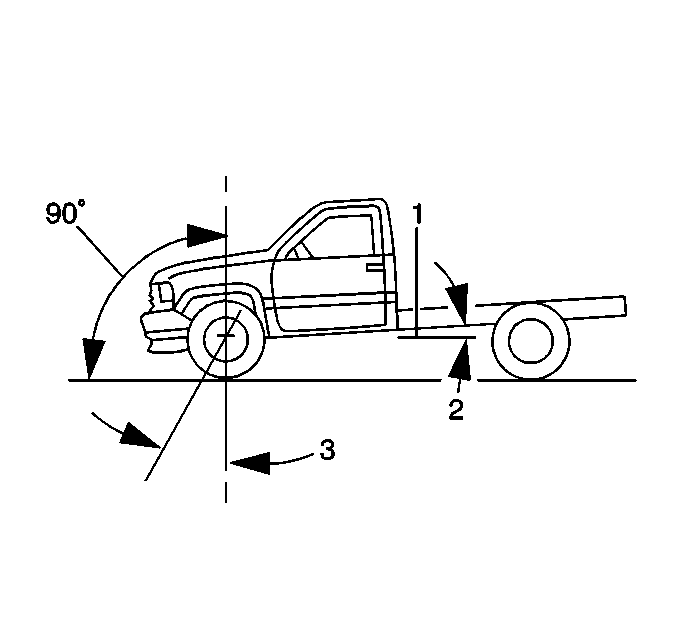
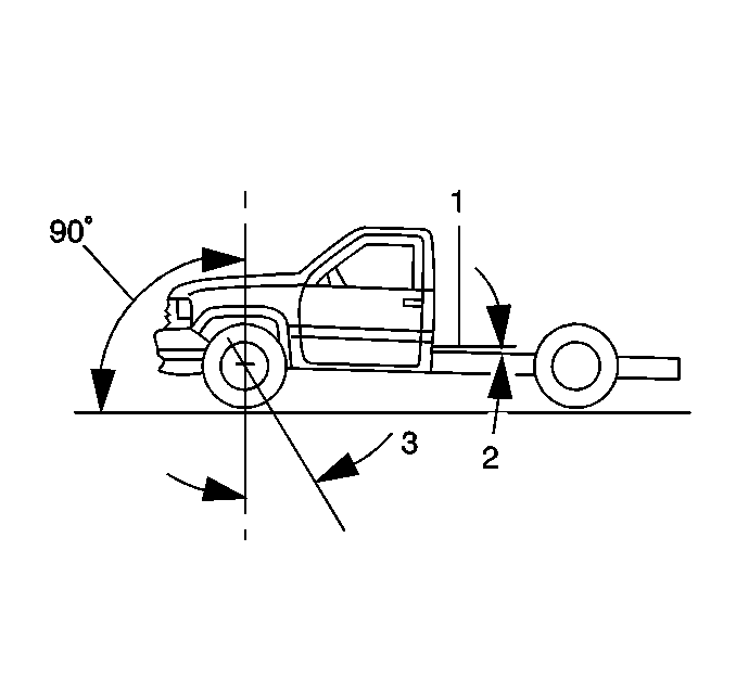
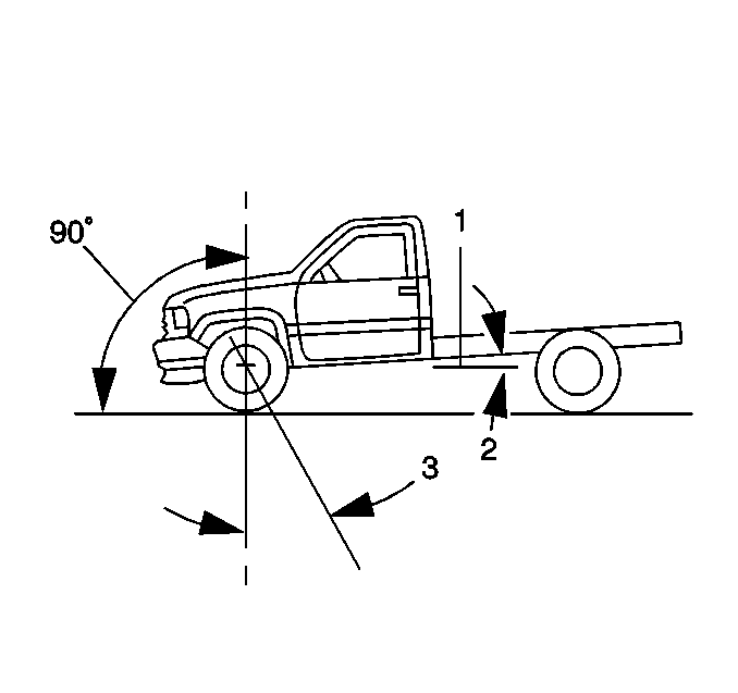
- Determine whether the frame angle is level, up-in-rear or down-in-rear.
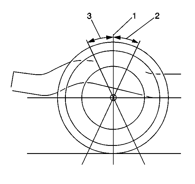
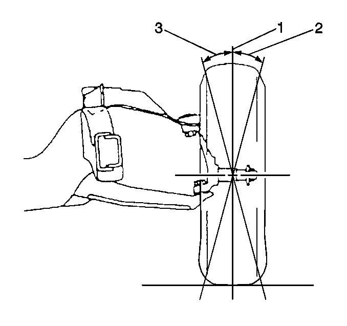
- A down-in-rear frame angle must be subtracted from a positive caster reading (3).
- An up-in-rear frame angle must be added to a positive caster reading (3).
- A down-in-rear frame angle must be added to a negative caster reading (3).
- An up-in-rear frame angle must be subtracted from a negative caster reading (3).
- Determine the caster (2, 3) angle.
- Determine the camber (2, 3) angle.
- If the caster and the camber angles are not within specifications, remove the frame bracket knockouts. Refer to Frame Bracket Knock Out Removal .
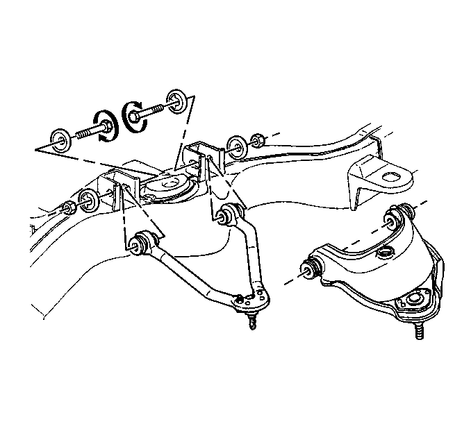
- Adjust the caster and the camber angle together by turning the cam bolts until the specifications have been met.
- Verify that the caster and the camber are within specifications. Refer to Wheel Alignment Specifications .
Important: All of the caster specifications are given with a frame angle at zero. Therefore, it is necessary to know the angle of the frame whether up-in-rear or down-in-rear before a corrected caster reading can be determined. The camber and the toe angle can be read as is from the alignment equipment.
The frame angle is the degree of tilt in the frame from the level position.
Notice: Use the correct fastener in the correct location. Replacement fasteners must be the correct part number for that application. Fasteners requiring replacement or fasteners requiring the use of thread locking compound or sealant are identified in the service procedure. Do not use paints, lubricants, or corrosion inhibitors on fasteners or fastener joint surfaces unless specified. These coatings affect fastener torque and joint clamping force and may damage the fastener. Use the correct tightening sequence and specifications when installing fasteners in order to avoid damage to parts and systems.
Tighten
Tighten the control arm bolts to 190 N·m (140 lb ft).
If the caster and camber are within specifications, Refer to Front Toe Adjustment .
