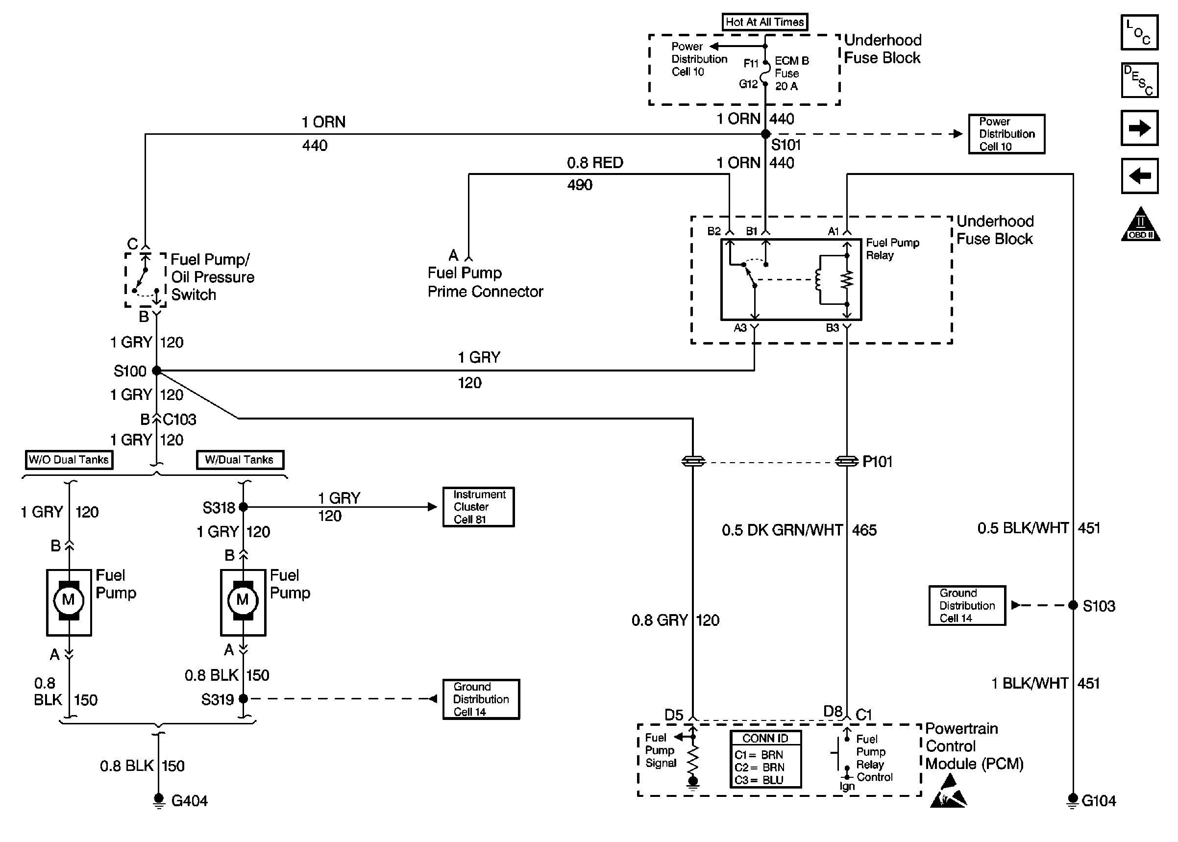
Refer to
Fuel Controls

Circuit Description
When the key is turned ON, the PCM energizes the fuel pump relay which sends voltage to the lift pump. The lift pump remains ON during the glow plug cycle. If the engine is not started immediately after the glow plug cycle, the PCM shuts the fuel lift pump OFF and waits until the engine starts. As a backup system to the fuel pump relay, the fuel lift pump can also be turned ON by the fuel pump/oil pressure switch. When the engine oil pressure reaches 28 kPa (4 psi), and the fuel pump relay does not complete the circuit, the fuel pump/oil pressure switch will close and complete the circuit to run the fuel lift pump.
Diagnostic Aids
Possible long crank times or a poor performance problem will exist.
Test Description
Number(s) below refer to the step number(s) on the Diagnostic Table.
-
Checks for proper operation of the fuel pump.
-
Checks the operation of the fuel pump by supplying 12 volts to the fuel pump control circuit.
-
Check the battery feed circuit to the fuel pump relay.
-
Checks for proper operation of the fuel pump relay.
Step | Action | Value(s) | Yes | No |
|---|---|---|---|---|
1 |
Important: Before clearing DTCs use the Scan Tool Capture Info to record freeze frame and failure records for reference, as data will be lost when Clear Info function is used. Was the Powertrain On-Board Diagnostic (OBD) System Check performed? | -- | ||
Does fuel pump operate during the glow plug cycle? | -- | |||
Apply a 12 volt fused jumper to the fuel pump test terminal. Does the fuel pump operate? | -- | |||
4 |
Does the fuel pump operate during glow plug cycle and then stop? | -- | ||
Is the test light ON? | -- | |||
6 | Connect an J 35616-200 unpowered test lamp between the fuel pump relay battery feed circuit harness connector and ground. Is the test light ON? | -- | ||
7 |
Is the test light ON during glow plug cycle and then OFF? | -- | ||
8 | Check for a proper connection at the fuel pump relay control connector terminal. Did you find a problem? | -- | ||
9 | Replace the fuel pump relay. Refer to Fuel Pump Relay Replacement . Is the action complete? | -- | ||
Does the engine continue to run? | -- | |||
11 |
Is the test light ON? | -- | ||
12 |
Is the test light ON? | -- | ||
13 | With an J 35616-200 unpowered test lamp connected to B+ probe the fuel pump ground terminal (vehicle side) of the chassis harness fuel pump connector. Is the test light ON? | -- | ||
14 | Repair the open in the battery feed circuit to the fuel pump relay harness connector terminal. Refer to Wiring Repairs in Wiring Systems. Is the action complete? | -- | -- | |
15 | Repair the open in the fuel pump relay ground circuit. Refer to Wiring Repairs in Wiring Systems. Is the action complete? | -- | -- | |
16 |
Did you find a problem? | -- | ||
17 | Check the oil pressure switch harness connector terminals for a proper connection. Did you find a problem? | -- | ||
18 | Replace the oil pressure switch. Refer to Engine Oil Pressure Sensor and/or Switch Replacement . Is the action complete? | -- | -- | |
19 | Replace the fuel lift pump. Refer to Fuel Lift Pump Replacement . Is the action complete? | -- | -- | |
20 | Repair the open between the fuel pump test terminal and the fuel pump feed circuit at the fuel pump harness connector. Refer to Wiring Repairs in Wiring Systems. Is the action complete? | -- | -- | |
21 | Repair the open in the fuel pump harness ground circuit. Refer to Wiring Repairs in Wiring Systems. Is the action complete? | -- | -- | |
22 | Repair the circuit as necessary. Refer to Wiring Repairs in Wiring Systems. Is the action complete? | -- | -- | |
23 | Repair the connection as necessary. Refer to Wiring Repairs in Wiring Systems. Is the action complete? | -- | -- | |
24 | Replace the PCM. Important: The new PCM must be programmed. Refer to Powertrain Control Module Replacement/Programming . Is the action complete? | -- | -- | |
25 |
Does the engine start and continue to run? | -- | ||
26 |
Are any additional DTCs displayed? | -- | Go to Applicable DTC Table | |
27 | Using the scan tool, select Capture Info, Review Info. Are any additional DTCs displayed that have not been diagnosed? | -- | Go to Applicable DTC Table | System OK |
