Circuit Description
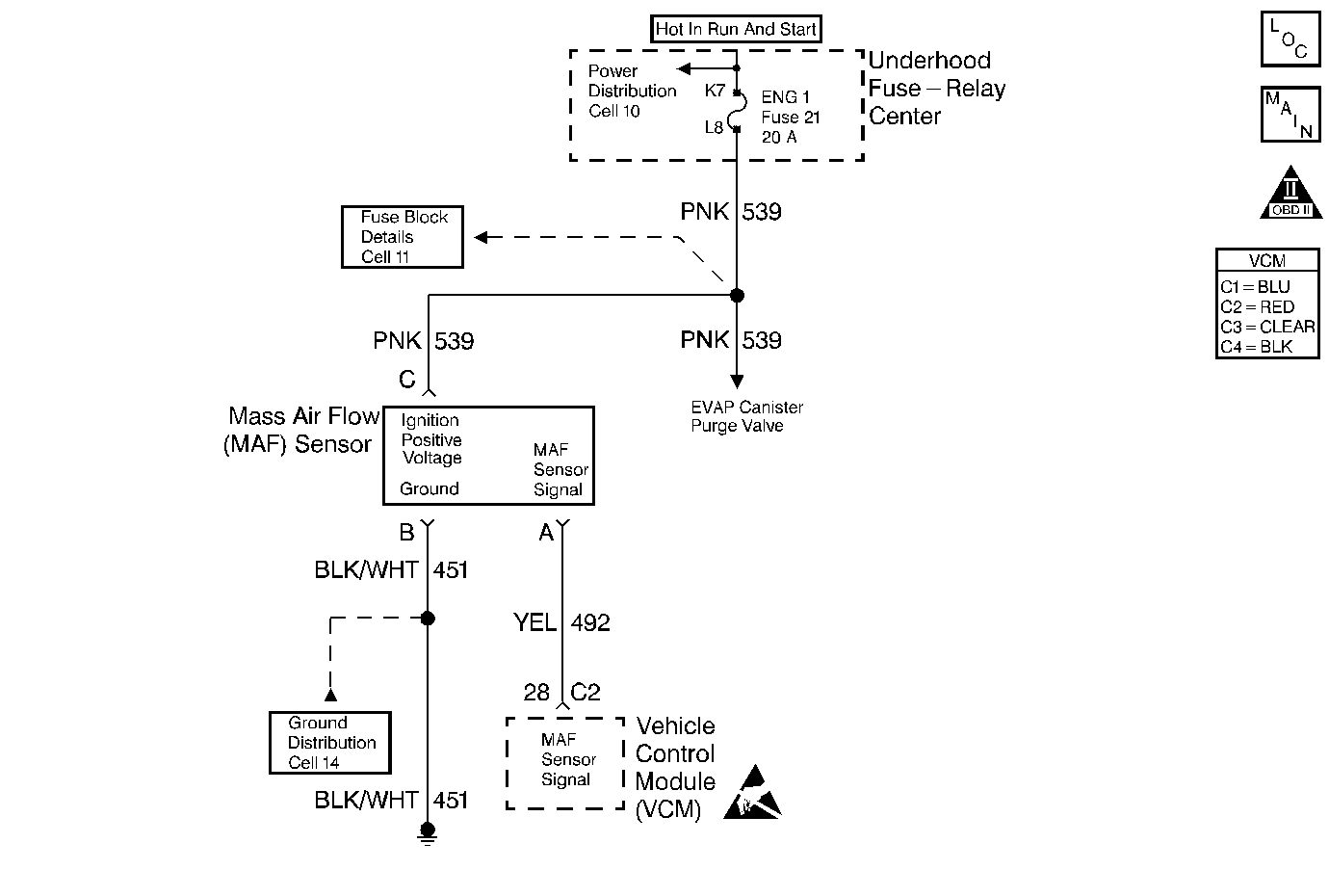
The mass air flow (MAF) sensor is an air flow meter. The control module supplies the MAF sensor a signal circuit. An ignition positive voltage circuit and a ground circuit are supplied to the MAF sensor by independent circuits. The MAF sensor heats a wire element, or grid, within the MAF sensor in order to maintain a calculated temperature. As inlet air flows across and cools the grid, the MAF sensor increases current flow to the grid in order to maintain the constant grid temperature. The MAF sensor converts the grid current flow into a frequency signal. The control module converts the MAF signal frequency into a grams per second value. During low air flow rates, such as at engine idle, the MAF sensor produces a low frequency signal. During high air flow rates, such as at wide open throttle-road load, the MAF sensor increases the frequency signal. The control module monitors the MAF sensor signal frequency in order to calculate the flow and mass of the air entering the engine.
The VCM monitors the MAF sensor air flow rate and compares this signal to a VCM calculated air flow rate. The calculated air flow is based on engine speed and barometric pressure. The VCM uses the MAP sensor in order to determine the barometric pressure when the ignition key is turned ON but before the engine is cranking or running. This DTC will be set if the MAF sensor signal airflow rate does not match the air flow rate calculated by the VCM.
Conditions for Running the DTC
| • | The engine is running |
| • | No active TP sensor DTCs |
| • | No active MAP sensor DTCs |
| • | No active EVAP DTCs |
| • | No active CKP sensor DTCs |
| • | No active IAT sensor DTCs |
| • | DTC P0401 not active |
| • | DTCs P0102 and P0103 not active |
| • | The system voltage is between 11-16 volts |
| • | The EVAP canister purge duty cycle is 99.6 percent or less |
| • | The TP sensor voltage is steady |
| • | The EGR duty cycle is less than 90 percent |
| • | The EGR pintle position is less than 90 percent |
| • | The throttle position is less than 9 percent |
| • | The above conditions exist for more than 2 seconds |
Conditions for Setting the DTC
| • | The actual MAF value is not equal to the calculated MAF value |
| • | The above condition exists for more than 5 seconds |
Action Taken When the DTC Sets
| • | The control module illuminates the malfunction indicator lamp (MIL) the first time the diagnostic runs and fails. |
| • | The control module will set the DTC and records the operating conditions at the time the diagnostic fails. The control module stores the failure information in the scan tools Freeze Frame/Failure Records. |
Conditions for Clearing the MIL or DTC
| • | The control module turns OFF the MIL after 3 consecutive drive trips when the test has run and passed. |
| • | A history DTC will clear if no fault conditions have been detected for 40 warm-up cycles. A warm-up cycle occurs when the coolant temperature has risen 22°C (40°F) from the startup coolant temperature and the engine coolant reaches a temperature that is more than 70°C (158°F) during the same ignition cycle. |
| • | Use a scan tool in order to clear the DTCs. |
Diagnostic Aids
Check for the following conditions:
| • | A skewed or stuck TP sensor. A problem with the TP sensor or TP sensor circuit can cause the VCM to incorrectly calculate the predicted mass air flow value. Observe the throttle angle with the throttle closed. If the throttle angle reading is not 0%, check for the following conditions: |
| - | The throttle plate is sticking or excessive deposits on the throttle plate or the throttle bore |
| - | The TP sensor signal circuit shorted to voltage |
| - | A poor connection or high resistance in the TP sensor ground circuit. |
| - | If none of the above conditions are noted and the throttle angle reading at closed throttle is not 0 percent, replace the TP sensor. |
| • | A misrouted harness. Inspect the MAF sensor harness in order to ensure that it is not routed too close to high voltage wires such as spark plug leads. |
| • | A damaged harness. Inspect the wiring harness for damage. If the harness appears to be OK, observe the scan tool while moving the connectors and the wiring harnesses related to the MAF sensor. A change in the display indicates the location of the fault. |
| • | A plugged intake air duct or dirty air filter element. A wide open throttle acceleration from a stop should cause the mass air flow displayed on a scan tool to increase from about 4-7 gm/s at idle to 100 gm/s or more at the time of the 1-2 shift. If not, check for a restriction. |
An intermittent may be caused by any of the following conditions:
| • | A poor connection |
| • | Rubbed through wire insulation |
| • | A broken wire inside the insulation |
Thoroughly check any circuitry that is suspected of causing the intermittent complaint. Refer to Intermittents and Poor Connections Diagnosis in Wiring Systems.
If a repair is necessary, refer to Wiring Repairs or Connector Repairs in Wiring Systems.
Test Description
The numbers below refer to the step numbers on the diagnostic table.
-
Correct any MAP sensor DTCs first. The value shown for the MAP sensor varies with altitude. The value decreases by approximately 3.0 kPa for every 1000 feet of altitude. 105 kPa is the approximate value displayed at or near sea level.
-
This step verifies that the problem is present at idle.
-
A voltage reading of less than 4.0 volts or over 6.0 volts at the MAF sensor signal circuit indicates a fault in the wiring or a poor connection.
-
This step verifies that the ignition positive voltage circuit and a good ground are available at the MAF sensor.
Step | Action | Value(s) | Yes | No | ||||||||||||||||||
|---|---|---|---|---|---|---|---|---|---|---|---|---|---|---|---|---|---|---|---|---|---|---|
1 |
Important: Before clearing the DTCs, use the scan tool Capture Info to save the Freeze Frame and Failure Records for reference. The control module's data is deleted once the Clear Info function is used. Did you perform the Powertrain On-Board Diagnostic (OBD) System Check? | -- | ||||||||||||||||||||
If any MAP or TP sensor DTCs are set, refer to the applicable DTC before proceeding.
Is the displayed value more than the value shown? | 105 kPa | |||||||||||||||||||||
3 |
Important: After removing the MAP sensor from the intake manifold, replace the MAP sensor to intake manifold seal. Important: The engine must remain operating during all steps that observe the MAP sensor display. Slightly raise the idle during testing in order to prevent engine stalling. Did you observe a skip or jump? | -- | ||||||||||||||||||||
4 | With the engine running apply 20 in Hg vacuum to the MAP sensor. Is the MAP sensor scan tool reading equal to or less than the specified value? | 34 kPa | ||||||||||||||||||||
5 | With the engine running disconnect the vacuum source from the MAP sensor. Does the MAP sensor reading match the baro reading? | -- | ||||||||||||||||||||
6 |
Did you find a problem? | -- | ||||||||||||||||||||
7 |
Does the scan tool display the specified value? | 0% | ||||||||||||||||||||
Does the scan tool indicate DTC P0101 Failed This Ignition? | -- | Go to Diagnostic Aids | ||||||||||||||||||||
9 |
Is the voltage near the specified value? | 5.0 V | ||||||||||||||||||||
Connect a test lamp between the MAF sensor ignition positive voltage and ground circuits at the MAF sensor harness connector. Is the test lamp ON? | -- | |||||||||||||||||||||
Is the voltage less than the specified value? | 4.5 V | |||||||||||||||||||||
12 |
Is the voltage near the specified value? | 0 V | ||||||||||||||||||||
13 | Connect a test lamp between the MAF sensor ignition positive voltage circuit and the chassis ground. Is the test lamp ON? | -- | ||||||||||||||||||||
14 |
Did you find a problem? | -- | ||||||||||||||||||||
15 |
Did you find a problem? | -- | ||||||||||||||||||||
16 | Repair the open in the ground circuit to the MAF sensor. Refer to Wiring Repairs in Wiring Systems. Is the action complete? | -- | -- | |||||||||||||||||||
17 | Repair the open in the ignition positive voltage circuit to the MAF sensor. Refer to Wiring Repairs in Wiring Systems. Is the action complete? | -- | -- | |||||||||||||||||||
18 | Repair the short to voltage in the MAF sensor signal circuit. Refer to Wiring Repairs in Wiring Systems. Is the action complete? | -- | -- | |||||||||||||||||||
19 | Replace the MAF sensor. Refer to Mass Airflow Sensor Replacement . Is the action complete? | -- | -- | |||||||||||||||||||
20 | Replace the MAP sensor. Refer to Manifold Absolute Pressure Sensor Replacement . Is the action complete? | -- | -- | |||||||||||||||||||
21 | Check for a poor connection at the VCM. Repair as necessary. Refer to Connector Repairs in Wiring Systems. Did you find a problem? | -- | Go to Step 23 | Go to Step 22 | ||||||||||||||||||
22 |
Is the action complete? | -- | -- | |||||||||||||||||||
23 |
Does the scan tool indicate the diagnostic Passed? | -- | ||||||||||||||||||||
24 | Does the scan tool display any additional undiagnosed DTCs? | -- | Go to the applicable DTC table | System OK |
