Info - Availability and Use of Fuel Return Volume Measuring Special Tool

| Subject: | Availability and Use of Fuel Return Volume Measuring Special Tool |
| Models: | 2004*-2007 Chevrolet F-Model T-Series Medium Duty Tilt Cab |
| 2004*-2007 GMC F-Model T-Series Medium Duty Tilt Cab |
| 2004*-2007 Isuzu F-Series Commercial Medium Duty Models |
| with 7.8L Diesel Engine (VIN 3 -- RPO LG4) |
| 2005-2007 Chevrolet W-Series Medium Duty Tilt Cab |
| 2005-2007 GMC W-Series Medium Duty Tilt Cab |
| 2005-2007 Isuzu N-Series Commercial Medium Duty Models |
| with 5.2L Diesel Engine (VIN 6 -- RPO 1L5) |
| *2004 with RPO CTF |
This bulletin is being revised to add the 2007 model year. Please discard Corporate Bulletin Number 05-06-04-062A (Section 06 -- Engine/Propulsion System).
Tool Part Number and Description
In certain "Crank No Start" conditions where no DTC is set, it can be difficult to isolate fuel system root causes.
A special tool has been developed to test the pressure limiter and fuel injectors. Using this tool correctly makes it possible to determine if a pressure limiter, fuel injector and/or supply pump is functioning properly.
Fuel Quantity Hoses Kit J 45873 (originally released to dealers servicing Duramax™ 6.6L Engine) and Fuel Tester Adapter Kit J 45873-100 are combined to make a complete kit for testing. Proper use and understanding of this tool is important to accurately diagnose the Common Rail Fuel System.
Service Information
Important: The 2006 model year 5.2L Fuel System Check section applies to 2005 model year vehicles. This information may be used for diagnostic assistance.
For 5.2L engines, detailed information regarding diagnostic procedures may be found in the 2006 model year service information.
Test Procedures
Important: Do not start the engine when performing these tests.
The following tests will measure the Fuel Return Volume of the pressure limiter and the fuel injectors. Return volume is measured during a 10 second cranking period.
To obtain the most accurate return volume reading, each test will need to be performed at least three times. After each test, the return volume must be recorded. After these tests are performed, the average return volume can be calculated to determine if the component meets the specification outlined in the current electronic service information.
Procedure: Pressure Limiter Leak Test
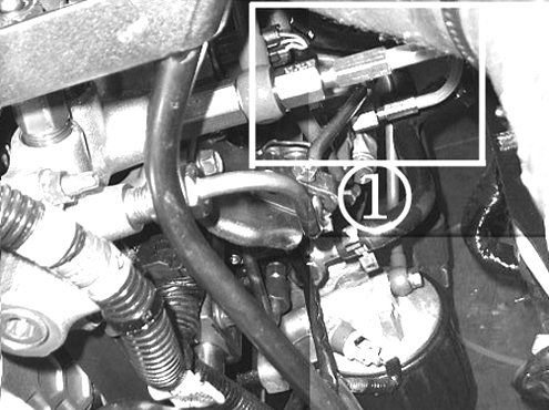
- Remove the pressure limiter banjo bolt, leaving the fuel return line in place.
- Install special tool fitting, J 45873-105 (1), into the pressure limiter banjo bolt location.
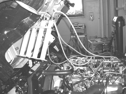
- Install the hose from the fitting to a graduated cylinder.
- Disconnect the injector inline harness connector.
- Crank the engine for 10 seconds.
- Turn the ignition OFF.
- Measure the fuel leak from the limiter and record the measurement.
- Repeat this test two more times and calculate the average fuel return rate.
- Compare the results to the appropriate engine specification.
- Reverse the steps to reassemble.

Procedure: Cylinder Head Return Volume Test
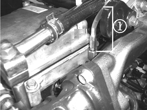
- Remove the cylinder head banjo bolt, leaving the fuel return pipe in place.
- Install special tool fitting, J 45873-102 (1), through the cylinder head return fuel pipe into the cylinder head.
- Install the hose from the fitting to a graduated cylinder.
- Be sure that the injector inline harness connector is disconnected.
- Crank the engine until clear lines are full and fuel begins to enter the graduated cylinder.
- Remove and empty the graduated cylinder.
- Replace the empty graduated cylinder.
- Crank the engine for 10 seconds.
- Turn the engine OFF.
- Measure the return fuel amount from the cylinder head and record the measurement.
- Repeat the test two more times and calculate the average fuel return rate.
- Compare the results to the appropriate engine specifications.
- Reverse the steps to reassemble.
Notice: The cylinder head test fitting has a coarse thread pitch. This fitting should only be installed at the cylinder head location. Attempted use in other locations may cause thread damage to the cylinder head and/or the tool itself.

Important: Fuel must be maintained in the hose between the cylinder head and the graduated cylinder. Always position graduated cylinders HIGHER than the hose end cylinder head connection. Draining this hose will cause inconsistent fuel return measurements.
Procedure: Fuel Injector Return Volume Test
- Remove each injector fuel return banjo bolt, leaving the injector return pipe in place.
- Install special tool fitting, J 45873-101, into each fuel injector.
- Install the hoses to each fitting and connect the hose to the graduated cylinders.
- Be sure that the injector inline harness connector is disconnected.
- Crank the engine until clear lines are full and fuel begins to enter the graduated cylinders.
- Remove and empty the graduated cylinders.
- Replace the empty graduated cylinders.
- Crank the engine for 10 seconds.
- Turn the engine OFF.
- Measure the return fuel amount from each injector and record the measurements.
- Repeat the test two more times and calculate the average fuel return rate.
- Compare the results to the appropriate engine specifications.
- Reverse the steps to reassemble.

Important: Fuel must be maintained in the hose between the cylinder head and the graduated cylinder. Always position graduated cylinders HIGHER than the hose end cylinder head connection. Draining this hose will cause inconsistent fuel return measurements.
Important: An injector with excessive return can mask other injector concerns. Be sure to retest flow rates when individual injectors are replaced.
