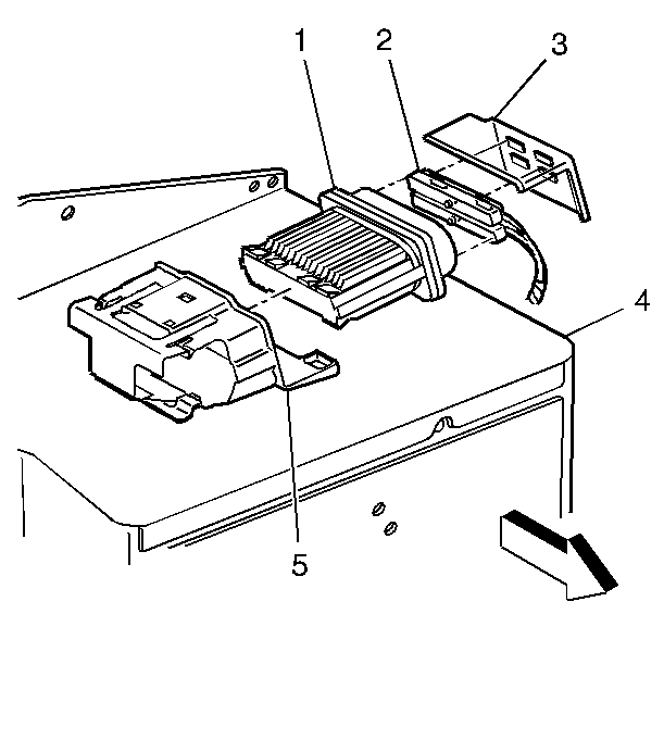
Important: Do not substitute a PCM from another vehicle for diagnosis.
Removal Procedure
Notice: Do not touch the connector pins or soldered components on the circuit
board in order to prevent possible electrostatic discharge (ESD) damage to
the PCM.
Important: The ignition should always be OFF when installing or removing the PCM
connectors.
- Open the hood.

- Remove the PCM housing
cover (3).
- Remove the PCM harness connectors (2).
- Remove the PCM bracket retaining bolt.
- Remove the PCM (1) from the bracket (5).
Installation Procedure

- Install the PCM (1) to
the bracket (5).
- Install the PCM bracket retaining bolt.
- Install the PCM harness connectors (2).
- Install the PCM housing cover (3)
- Program the EEPROM if a new PCM is being installed.
EEPROM Programming
Important: The following must be performed anytime the PCM is replaced.
| • | The Engine Oil Life Monitor Reset procedure. |
| • | The PTO FAst Idle and Fast Idle System Programming procedure (if
equipped). |
Setup
- Ensure that the following conditions have been met:
| • | The battery is fully charged. |
| • | The scan tool cable connection at the DLC is secure. |
- Program the PCM using the latest software matching the vehicle.
Refer to the Techline terminal/equipment users instructions.
- If the PCM fails to program, proceed as follows:
| • | Ensure that all PCM connections are OK. |
| • | Check the Techline terminal/equipment for the latest software
version. |
| • | Attempt to program the PCM. Replace the PCM if the PCM still cannot
be programmed properly. |
Functional Check
- Perform the On-Board Diagnostic System Check.
- Start the engine and run for 1 minute.
- Scan for DTCs using the scan tool.


