Refer to
Cell 20: Powertrain Control Module, Ignition Coils
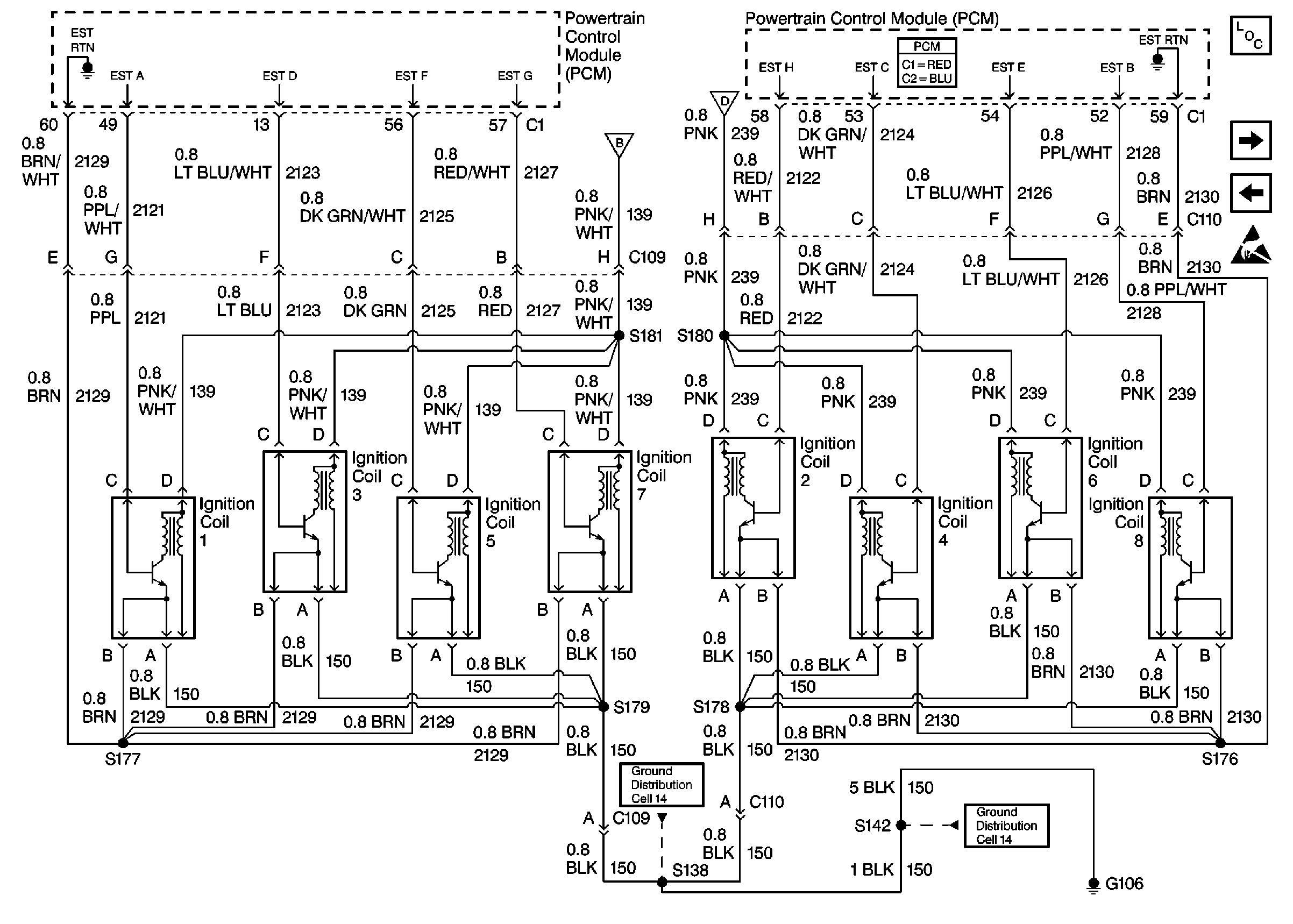
Circuit Description
A Crankshaft Position (CKP) sensor determines the engine crankshaft position. The sensor is mounted and protrudes into the engine front cover. The sensor is near a slotted reluctor ring on the crankshaft. The rotation of the slotted reluctor ring causes a magnetic flux change in the sensor. This produces a voltage signal from the electronic Ignition Control Module (ICM). The signal creates the reference pulses needed by the Powertrain Control Module (PCM). These signals trigger the correct ignition coil to fire, at the correct time.
The ignition system on this engine uses an individual ignition coil/module for each cylinder. The PCM controls the ignition system operation. There are eight Ignition Control (IC) circuits, one per cylinder, that connect the PCM and the ignition coil/modules. Each ignition coil/module has an ignition positive voltage circuit, a ground circuit, and a reference low circuit. The PCM causes a spark to occur by grounding the IC circuit, which signals the ignition module to trigger the ignition coil and fire the spark plug. The PCM controls the sequencing and timing.
Diagnostic Aids
The following may cause an intermittent:
| • | Check for poor connections. Check for adequate terminal tension. |
| • | Corrosion |
| • | Mis-routed harness |
| • | Rubbed through wire insulation |
| • | Broken wire inside the insulation |
For an intermittent condition, refer to Symptoms .
Test Description
The numbers below refer to the step numbers on the diagnostic table.
Important: Be sure to use the same diagnostic equipment for all measurements.
-
This step will identify the misfiring cylinders. The spark tester requires a minimum of 25,000 volts to operate. It may be necessary to use the spark tester on all of the cylinders because the ignition system may provide enough voltage to run the engine but not enough to operate a spark plug under a heavy load. If you were sent here from the Engine Cranks But Will Not Run table, check for a faulty connection at the engine ground terminal.
-
This step determines if the malfunction is affecting one cylinder or an entire bank of the ignition system.
-
This test checks for a short to voltage at the ignition control (IC) signal circuit between the ignition coil/module and the PCM.
-
This test will determine which side of the 8-way connector the malfunction is located.
-
This test checks for a short to ground at the ignition control (IC) signal circuit between the PCM connector and the 8-way connector.
-
This step completes the testing of the ignition system for a problem that will cause an entire bank to malfunction.
Step | Action | Value(s) | Yes | No | ||||||||||
|---|---|---|---|---|---|---|---|---|---|---|---|---|---|---|
1 | Did you perform the Powertrain On-Board Diagnostic (OBD) System? | -- | ||||||||||||
Does the spark jump the tester? | 50-200 RPM | |||||||||||||
3 | Visually/physically inspect the ignition wires for the following conditions:
Was a problem found and repaired? | -- | ||||||||||||
4 |
Is the ignition wire resistance less than the specified value? | 700 ohms | ||||||||||||
5 | Remove the spark plugs from the cylinders that corresponds to the cylinders that did not indicate the specified value of RPM drop. Does the spark plug appear to be OK? | 50-200 RPM | ||||||||||||
6 |
Important:: If the Injector Coil Test Procedure checks to be OK, refer to Engine/Engine Mechanical.
Did the symptom move with the spark plug? | -- | Go to | |||||||||||
7 | Are the spark plugs oil or coolant fouled? | -- | Go to Spark Plug Visual Diagnosis in Engine Mechanical | |||||||||||
8 |
Important:: If the Fuel system checks to be OK, refer to Engine /Engine Mechanical. Are the spark plugs fuel fouled? | -- | Go to Fuel System Diagnosis | |||||||||||
9 |
Important:: If the Injector Coil Test Procedure checks OK, refer to Engine /Engine Mechanical. Inspect the spark plugs for any signs of the following conditions;
Were any of the above conditions found? | -- | ||||||||||||
Was no spark present at only one cylinder? | -- | |||||||||||||
11 |
Does the test lamp illuminate? | -- | ||||||||||||
12 |
Does the test lamp illuminate? | -- | ||||||||||||
13 |
Does the test lamp illuminate? | -- | ||||||||||||
14 |
Is the frequency within the specified values? | 3.0-2.0- Hz | ||||||||||||
| 1.0 volt | |||||||||||||
Is the frequency within the specified values? | 3.0-2.0- Hz | |||||||||||||
Does the DMM indicate continuity? | -- | |||||||||||||
18 |
Does the test lamp illuminate? | -- | ||||||||||||
19 |
Does the test lamp illuminate? | -- | ||||||||||||
20 |
Does the test lamp illuminate? | -- | ||||||||||||
21 |
Does the test lamp illuminate? | -- | ||||||||||||
Does the test lamp illuminate? | -- | |||||||||||||
23 |
Does the DMM indicate continuity? | -- | ||||||||||||
24 | Check for poor connections/terminal tension at the PCM harness connector. Refer to Intermittents and Poor Connections Diagnosis in Wiring Systems. Was a problem found and repaired? | -- | ||||||||||||
25 | Replace the faulty ignition wire. Is the action complete? | -- | -- | |||||||||||
26 | Replace or re-gap the spark plugs. If improper gap is found, adjust the spark plug gap using a wire type gauge. Is the action complete? | -- | -- | |||||||||||
27 | Replace the faulty spark plugs. Is the action complete? | -- | -- | |||||||||||
28 | Repair an open ignition positive voltage circuit between the ignition coil/module and the splice. Is the action complete? | -- | -- | |||||||||||
29 | Repair an open ground circuit between the ignition coil/module and the splice. Is the action complete? | -- | -- | |||||||||||
30 | Repair an open ground circuit between the 8-way connector and the splice. Is the action complete? | -- | -- | |||||||||||
31 | Repair an open reference low circuit between the ignition coil/module and the splice. Is the action complete? | -- | -- | |||||||||||
32 | Repair an open reference low circuit between the 8-way connector and the splice. Is the action complete? | -- | -- | |||||||||||
33 | Repair an open reference low circuit between the 8-way connector and the PCM. Is the action complete? | -- | -- | |||||||||||
34 | Replace the ignition coil/module. Is the action complete? | -- | -- | |||||||||||
35 | Repair a short to voltage to the ignition control signal circuit between the ignition coil/module and the PCM. Is the action complete? | -- | -- | |||||||||||
36 | Repair a short to ground at the ignition control signal circuit between the 8-way connector and the PCM. Is the action complete? | -- | -- | |||||||||||
37 | Repair a short to ground or an open at the ignition control signal circuit between the 8-way connector and the ignition coil/module. Is the action complete? | -- | -- | |||||||||||
38 | Repair an open ground circuit between the 8-way connector and the engine ground. Is the action complete? | -- | -- | |||||||||||
39 | Repair an open ignition control signal circuit between the 8-way connector and the PCM. Is the action complete? | -- | -- | |||||||||||
40 | Repair an open ignition positive voltage circuit between the 8-way connector (engine side) and the splice . Is the action complete? | -- | -- | |||||||||||
41 |
Is the action complete? | -- | -- | |||||||||||
42 |
Is the action complete? | -- | -- | |||||||||||
43 | Operate the vehicle within the conditions under which the original symptom was noted. Does the system now operate properly? | -- | System OK |
