Circuit Description
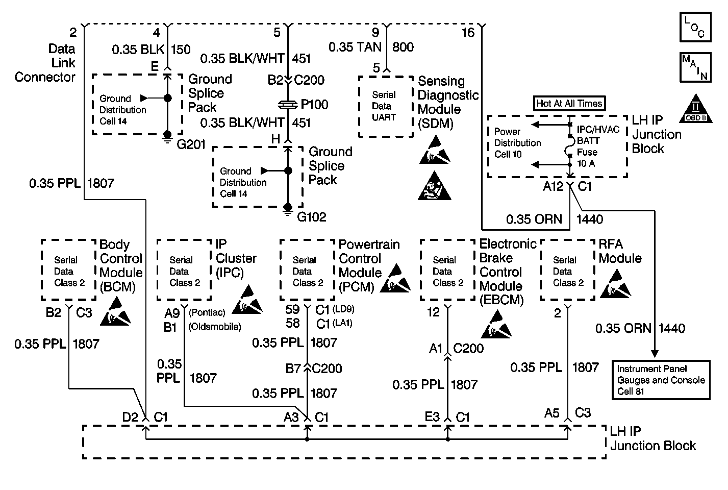
A class 2 serial data communications system is used on this vehicle in order to allow various modules to communicate and share information with each other. This allows for the reduction of the vehicle wiring, and for the transmission and reception of multiple signals over a single wire. The messages carried on the class 2 serial data stream are also prioritized. If two messages attempt to establish communications on the data line at the same time, the message with the higher priority will continue. The message with the lower priority message will wait.
All modules on the class 2 serial data line send out a periodic identifier message. The powertrain control module (PCM) is listening for the identifier messages from the following modules:
| • | The electronic brake control module (EBCM) |
| • | The body control module (BCM) |
| • | The instrument panel cluster (IPC) |
If the PCM does not receive an identifier message from a module, the PCM assumes that there is a loss of communication and a DTC is stored. A DTC P1626 will set after the engine has been started, theft has passed, and there is lost of communication between the PCM and the BCM. Since this DTC P1626 set after the engine has been started, the theft protection is bypassed at subsequent key ups. The vehicle will start, but as long as DTC P1626 is set there is no theft protection.
Conditions for Running the DTC
| • | The ignition is ON. |
| • | The system voltage is between 11 and 16 volts. |
Conditions for Setting the DTC
The PCM has lost communication with the body control module (BCM) after the PCM received a theft passed message from the BCM.
Action Taken When the DTC Sets
| • | The PCM will record operating conditions at the time the diagnostic fails. This information will store in the Freeze Frame and Failure Records buffers. |
| • | A history DTC stores. |
Conditions for Clearing the MIL/DTC
| • | A history DTC will clear after 40 consecutive warm up cycles without a fault. |
| • | Use a scan tool can clear the DTCs. |
Diagnostic Aids
Attempting to start the vehicle by bypassing the passlock ll system or by substituting parts without performing the password learn procedure may set a DTC P1631 and a P1632.
If no password is received, a DTC U1064 and P1632 may be set.
An intermittent may be caused by the following conditions:
| • | A poor electrical terminal connection |
| • | A broken wire inside the insulation |
Thoroughly inspect any suspected circuitry for the following items:
| • | Backed out terminals or improper mating |
| • | Improperly formed or damaged terminals |
| • | Poor terminal to wiring connections |
| • | Physical damage to the wiring harness |
| • | Corrosion |
Test Description
The numbers below refer to the step numbers on the diagnostic table.
Step | Action | Values | Yes | No | ||||||
|---|---|---|---|---|---|---|---|---|---|---|
1 | Did you perform the Powertrain On-Board Diagnostic (OBD) System Check? | -- | Go to Step 2 | |||||||
2 |
Dioes the scan tool indicate DTC P1626 Failed This Ignition? | -- | ||||||||
3 |
Did DTC P1626 reset? | -- | System OK | |||||||
4 | Was the BCM the module that stopped communicating? | -- | Go to Diagnostic System Check - Body Control System in Body Control System | |||||||
5 | With the scan tool, attempt to communicate with the BCM. Does the BCM communicate? | -- | Go to DTC U1016 Loss of Communications with PCM or DTC U1001-U1254 Loss of XXX Communications in Data Link Communications | |||||||
6 | Are any body control module DTCs set? | -- | Go to Diagnostic System Check - Body Control System in Body Control System | |||||||
Important:: The replacement PCM must be programmed. Refer to Powertrain Control Module Replacement/Programming . Did you complete the replacement? | -- | -- | ||||||||
8 |
Does the DTC reset? | -- | System OK |
