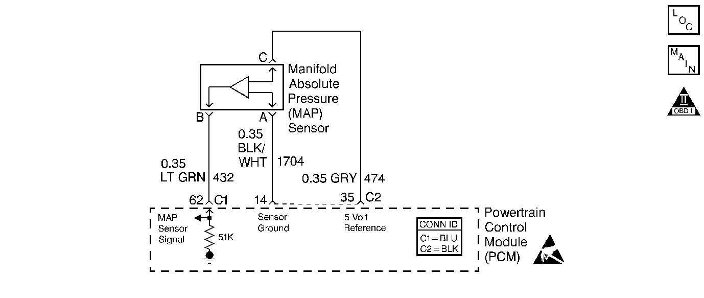
Circuit Description
The Powertrain Control Module (PCM) uses the manifold absolute pressure (MAP) sensor in order to control the fuel delivery and the ignition timing. The MAP sensor measures the changes in the intake manifold pressure which result from engine load, or intake manifold vacuum, and the RPM changes, and converts these into voltage outputs. The Powertrain Control Module (PCM) sends a 5 volt reference voltage to the MAP sensor. As the manifold pressure changes, the output voltage of the MAP sensor also changes. By monitoring the MAP sensor output voltage, the PCM knows the manifold pressure. A lower pressure, or lower voltage, output voltage will be approximately 1.0 to 1.5 volts at idle. Higher pressure, or higher output voltage will be approximately 4.5 to 4.8 volts at wide open throttle (WOT). The MAP sensor is also used to measure barometric pressure, allowing the PCM to make adjustments for different altitudes.
Conditions for Running the DTC
| • | DTCs P0122 or P0123 are not set. |
| • | The throttle position (TP) sensor is less than 12 percent. |
| • | The vehicle speed sensor is less than 2 km/h (1 mph). |
| • | The engine run time is more than 20 to 40 seconds. |
Conditions for Setting the DTC
| • | The MAP sensor is more than 82 kPa. |
| • | The above condition is met for at least 1.25 seconds. |
Action Taken When the DTC Sets
| • | The malfunction indicator lamp (MIL) will illuminate after two consecutive ignition cycles in which the diagnostic runs with the fault active. |
| • | The Powertrain Control Module (PCM) will record operating conditions at the time the diagnostic fails. This information will be stored in the Freeze Frame and Failure Records buffers. |
| • | A history DTC is stored. |
| • | The coolant fan turns ON. |
| • | The PCM will substitute a fixed MAP value and will use throttle position (TP) to control the fuel delivery. The scan tool will not show the defaulted value. |
| • | The PCM will use a fixed BARO value of 90 kPa. |
| • | The vehicle will operate in Open Loop when the vehicle is less than 8 km/h (5 mph). The vehicle will operate in Closed Loop when the vehicle is more than 8 km/h (5 mph). |
Conditions for Clearing the MIL/DTC
| • | The MIL will turn OFF after three consecutive ignition cycles in which the diagnostic runs without a fault. |
| • | A history DTC will clear after 40 consecutive warm-up cycles without a fault. |
| • | Use a scan tool to clear the DTCs. |
Diagnostic Aids
With the ignition switch ON and the engine stopped, the manifold pressure is equal to atmospheric pressure and the signal voltage will be high.
This information is used by the PCM as an indication of the vehicle altitude. Comparison of this reading with a known good vehicle with the same sensor is a good way to determine the accuracy of a suspect sensor. Readings should be the same ± 0.4 volt.
DTC P0108 may set as a result of a misfire. If a misfire is present, repair the cause of misfire before using this table. The misfire counters may be used to determine which cylinder is misfiring.
DTC P0108 may also set when attempting to start a vehicle that has run out of fuel.
If a DTC P0108 is intermittent, refer to Symptoms or Manifold Absolute Pressure Sensor Output Diagnosis 2.2L for further diagnosis.
Important: After repairs, use scan tool Fuel Trim Reset function to reset the long-term fuel trim to 128 (0 percent).
Test Description
The numbers below refers to the step numbers on the Diagnostic Table.
-
This step simulates the conditions for a DTC P0107. If the PCM recognizes the change, the PCM, the 5.0 volt reference, and the MAP sensor signal circuits are OK.
-
This step will determine if DTC P0108 is the result of a hard malfunction or an intermittent condition.
-
This step looks for an open in the MAP sensor ground circuit.
-
When the MAP sensor signal circuit is shorted to battery voltage, the throttle position (TP) will display above 0 percent at all times and the A/C High Side will display high. The vehicle will also remain in Open Loop.
-
The MAP sensor vacuum source should only supply vacuum to the MAP sensor. Inspect the vacuum port for a restriction caused by casting flash.
-
The replacement PCM must be programmed and the Crankshaft Position System Variation Learn procedure must be performed.
Step | Action | Value(s) | Yes | No | ||||
|---|---|---|---|---|---|---|---|---|
1 | Did you perform the Powertrain On Board Diagnostic (OBD) System Check? | -- | ||||||
2 | Start and idle the engine. Does the MAP voltage read more than or equal to the specified value? | 4.0 V | ||||||
Does the MAP voltage read the specified value or less? | 1.0 V | |||||||
Operate the vehicle within the Freeze Frame conditions and Conditions for Running the DTC as specified in the supporting text. Does the MAP voltage read the specified value or more? | 4.0 V | Go to Diagnostic Aids | ||||||
Does the test lamp illuminate? | -- | |||||||
Did you find and correct the condition? | -- | |||||||
7 |
Does the DMM display read near the specified value? | 5.0 V | ||||||
Did you find a problem? | -- | |||||||
9 |
Did you find and correct the condition? | -- | ||||||
10 | Repair the vacuum source as necessary. Did you complete the repair? | -- | -- | |||||
11 |
Did you find and correct the condition? | -- | ||||||
12 |
Did you find and correct the condition? | -- | ||||||
|
Important:: The replacement PCM must be programmed. Refer to Powertrain Control Module Replacement/Programming . Replace the PCM. Refer to Powertrain Control Module Replacement . Did you complete the replacement? | -- | -- | ||||||
14 | Replace the MAP sensor. Refer to Manifold Absolute Pressure Sensor Replacement . Did you complete the replacement? | -- | -- | |||||
15 |
Does the DTC reset? | -- | System OK |
