Tools Required
| • | J 44015 Steering Linkage Installer |
| • | SA91100C Tie Rod Separator |
Removal Procedure
- Remove as much power steering fluid from the power steering fluid reservoir as possible if equipped with hydraulic power steering (HPS).
- Place drain pans under the vehicle as needed if equipped with HPS.
- Remove the front tire/wheel assemblies. Refer to Tire and Wheel Removal and Installation .
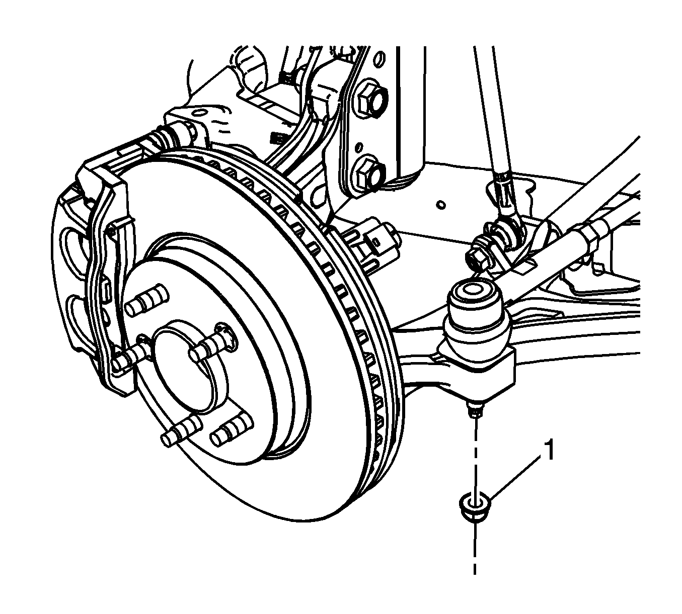
- Remove both steering linkage outer tie rod nuts (1) and discard them.
- Use separator SA91100C to separate the steering linkage outer tie rods from the steering knuckles.
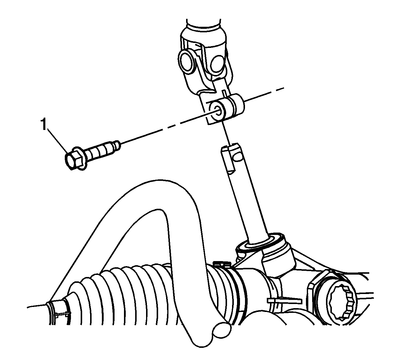
- Remove the steering shaft coupling bolt (1) and disconnect the steering shaft coupling from the steering gear.
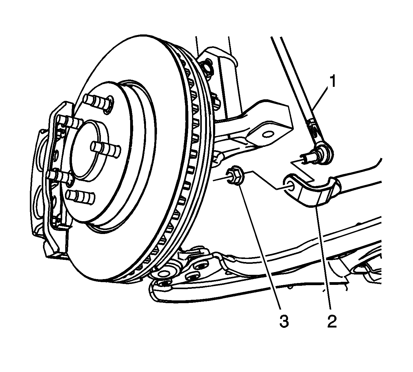
- Remove the stabilizer shaft link nuts (3) and disconnect the stabilizer shaft links (1) from the stabilizer shaft (2).
- Remove the steering gear bolts and nuts.
- Rotate the stabilizer shaft to provide clearance for the steering gear.
- Remove the power steering gear inlet hose bracket bolt (1) if equipped with HPS.
- Disconnect the power steering gear inlet hose (2) and the power steering cooler hose (1) from the steering gear if equipped with HPS.
- Maneuver and remove the steering gear through the left wheelhouse opening.
Notice: Secure the steering wheel utilizing a strap to prevent rotation. Locking of the steering column will prevent damage and a possible malfunction of the SIR system. The steering wheel must be secured
in position before disconnecting the following components:
• The steering column • The intermediate shaft • The steering gear
Notice: Do not free the ball stud by using a pickle fork or a wedge-type tool. Damage to the seal or bushing may result.

Important: Do not reuse the old O-Ring seals.
Installation Procedure
- Maneuver the steering gear into the vehicle through the left wheelhouse opening. Make sure that the steering gear bushings are centered in the frame.
- Install the steering gear bolts and nuts.
- Connect the steering shaft coupling to the steering gear and install a new steering shaft coupling bolt (1).
- Connect the power steering gear inlet hose (2) and the power steering cooler hose (1) to the steering gear if equipped with HPS.
- Install the power steering gear inlet hose bracket bolt (1) if equipped with HPS.
- Connect the stabilizer shaft links (1) to the stabilizer shaft (2) and install the stabilizer shaft link nuts (3).
- Use installer J 44015 to seat the steering linkage outer tie rods.
- Install the steering linkage outer tie rod nuts (1).
- Clean any excess fluid from the vehicle and remove the drain pans if equipped with HPS.
- Fill and bleed the power steering system if equipped with HPS. Refer to Power Steering System Bleeding
- Install the front tire/wheel assemblies. Refer to Tire and Wheel Removal and Installation .
- Adjust the front toe. Refer to Front Toe Adjustment .
Notice: Refer to Fastener Notice in the Preface section.
Important: Hand start all steering gear bolts and nuts before finalizing any torques.
Tighten
Tighten the bolts to 110 N·m (81 lb ft).
Tighten
Tighten the bolt to 34 N·m (25 lb ft).
Important: Use NEW O-Ring seals.
Tighten
Tighten the bolt to 9 N·m (80 lb in)
Tighten
Tighten the nuts to 65 N·m (48 lb ft).
Tighten
Tighten installer
J 44015
to 40 N·m (30 lb ft)
Tighten
Tighten the nuts to 25 N·m (18 lb ft) plus 90 degrees.
