For 1990-2009 cars only
Installation Procedure
Tools Required
| • | J 28467-B Universal Engine Support Fixture |
| • | J 28467-7A Bolt Hook |
| • | J-28467-13 Engine Support Fixture Adapters |
| • | J 28467-34 Lift Hook Wing Nut and Washer |
| • | J 36462-A Engine Support Adapter Leg Set |
| • | J 42451-1 Engine Support Adapter |
- Remove the fuel injector sight shield. Refer to Fuel Injector Sight Shield Replacement .
- Remove the engine mount bracket. Refer to Engine Mount Bracket Replacement - Right Side .
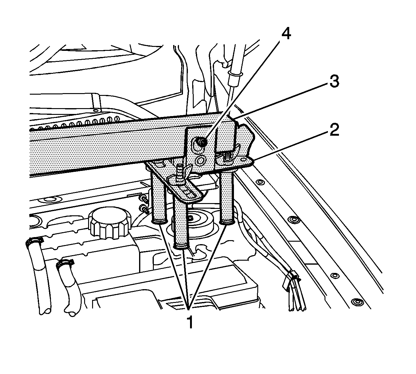
- Install three J-28467-13 (1) and two J 28467-5 strut tower adapters (2) to the top of the left and right strut tower.
- Install a 127 cm (50 in) engine support fixture cross bar J 28467-B (3) transversely across the vehicle between both J 28467-5 strut tower adapters (2).
- Insert safety pins J-28467-10 (4) through the J 28467-5 strut tower adapters (2) and the cross bar (3) to prevent movement.
- Support engine using a hydraulic jack.
- Remove right side engine mount. Refer to Engine Mount Replacement - Right Side .
- Remove camshaft position sensor. Refer to Camshaft Position Sensor Replacement - Bank 1 (Right Side) Intake .
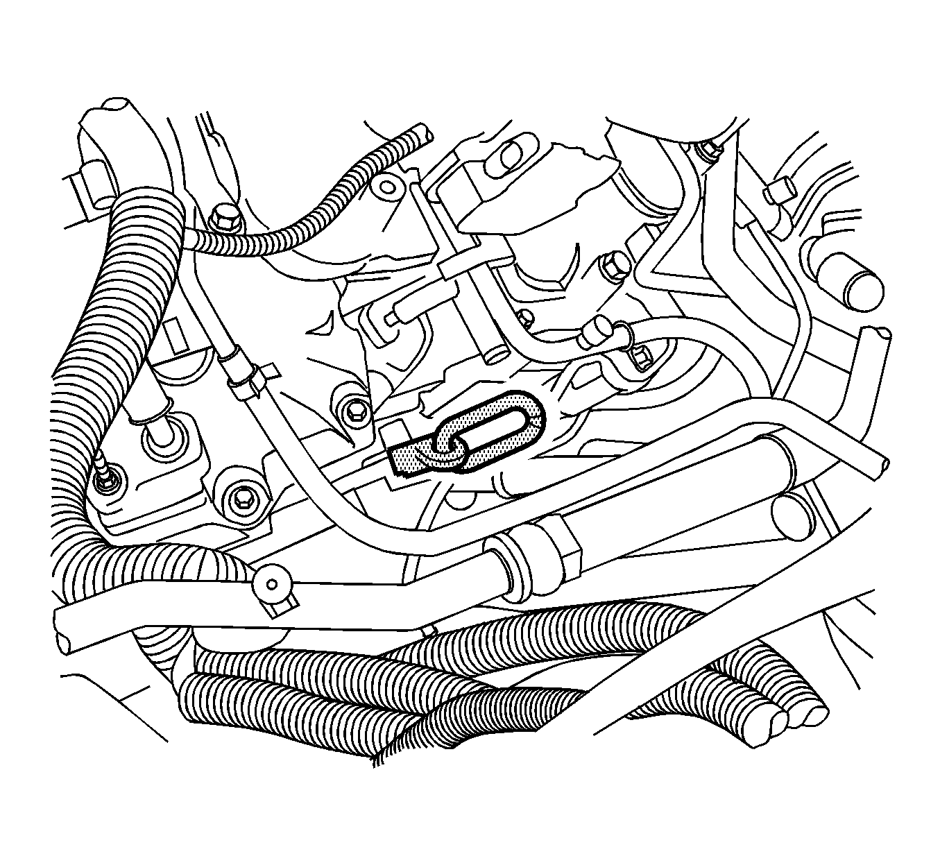
- Install the engine support bracket J 42451-1 to the left side of engine.
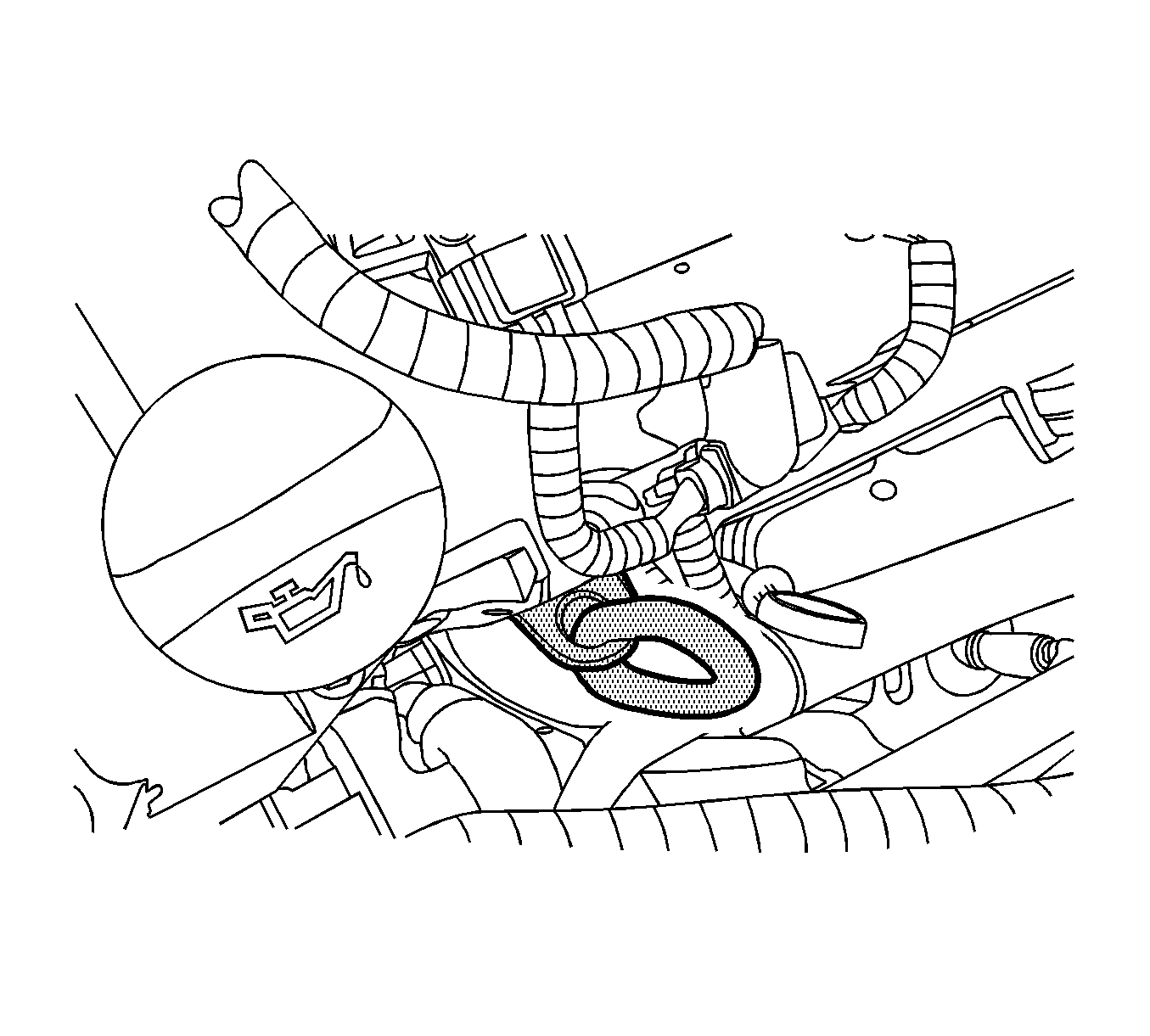
- Install the engine support bracket (1) J 42451-1 and a 3.9 cm (1.5 in) spacer (2), to the right side of engine.
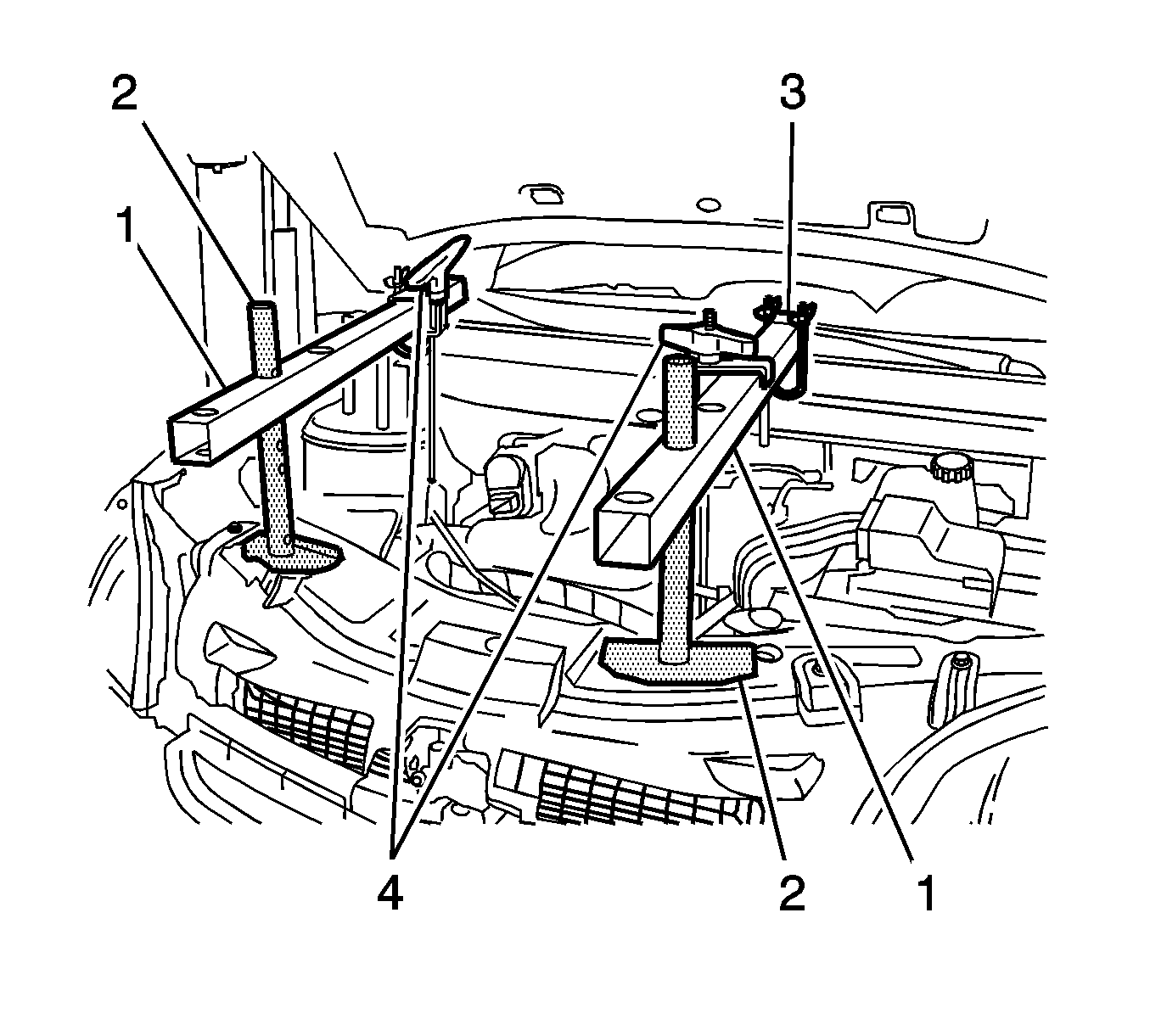
- Position two 58 cm (23 in) engine support fixture cross bars (1) longitudinally with two J 36462-A leg assembly (2).
- Install two J 28467-1A clamp (3) to secure the longitudinal mounted cross bar to the transverse mounted cross bar.
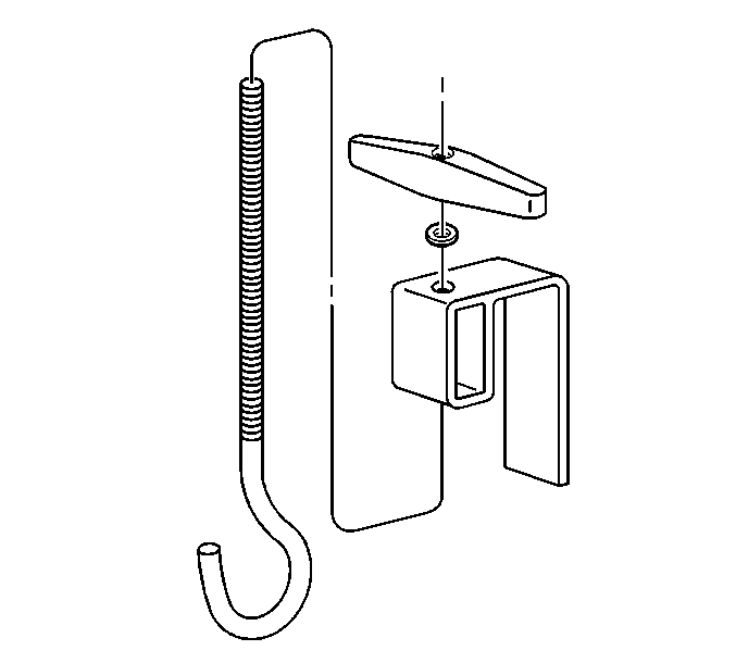
- Assemble the lift hook wing nut J 28467-34 and the lift hook bracket J-28467-6A to the lift hook J 28467-7A .
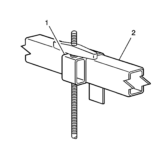
- Install the lift hook and bracket assembly (1) to the longitudinal mounted cross bar (2).
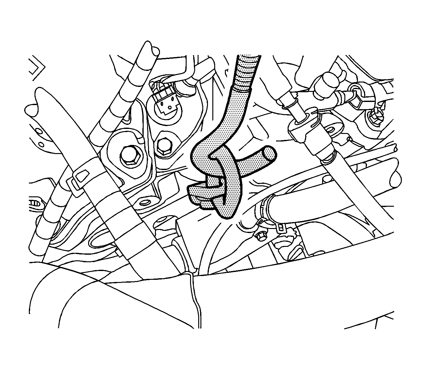
- Position the J 28467-7A lift hook to the right engine lift bracket J 42451-1 (2).
- Assemble the lift hook wing nut J 28467-34 and the lift hook bracket J-28467-6A to the lift hook J 28467-7A .
- Install the lift hook and bracket assembly (1) to the longitudinal mounted cross bar (2).
- Position the J 28467-7A bolt hook (1) to the left engine lift bracket J 42451-1 (2).
- Evenly tighten both wing nuts J 28467-34 (4) until the engine weight is supported by the engine support fixture and no longer carried by the engine mounts.
