For 1990-2009 cars only
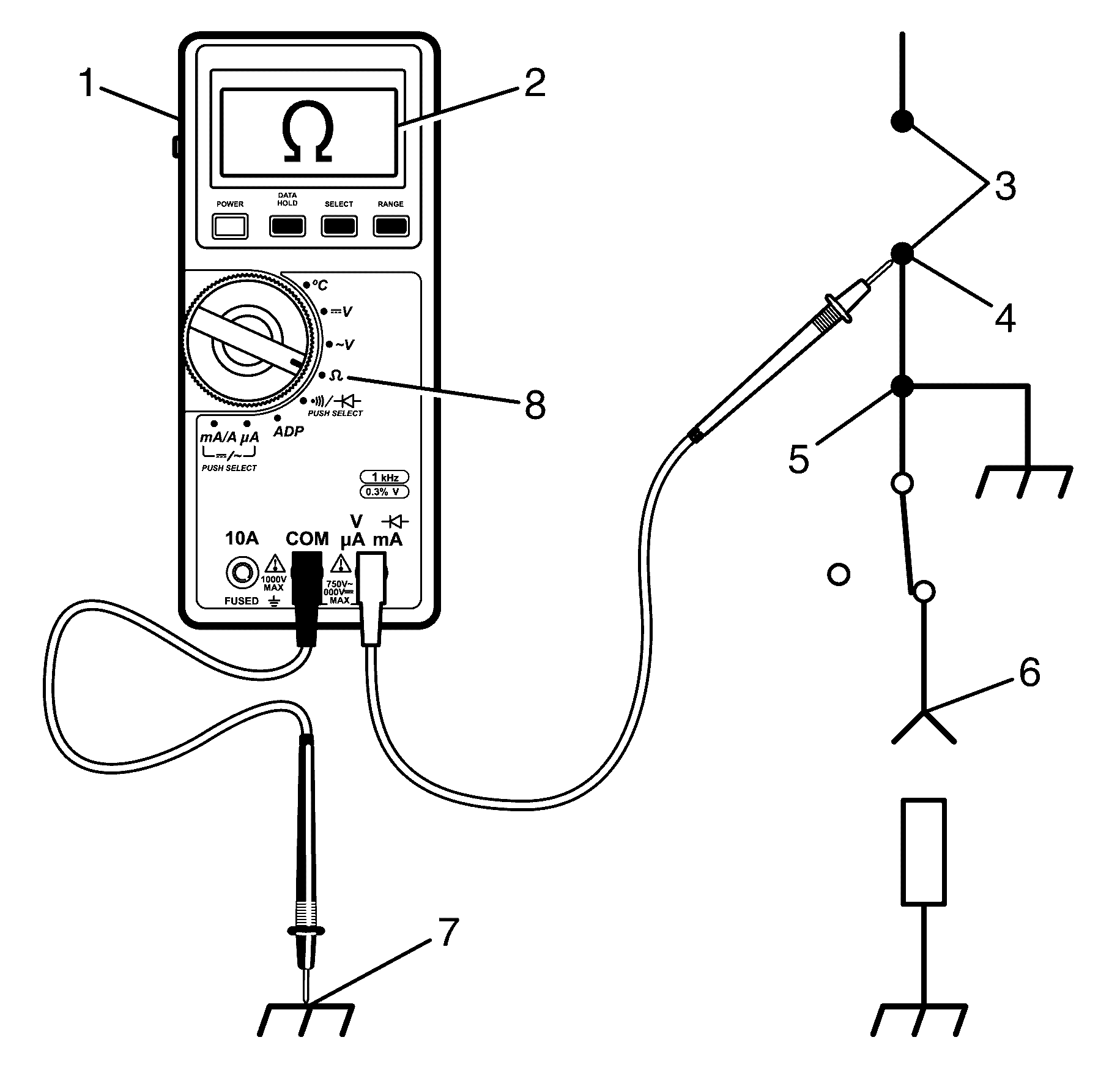
Notice: Refer to Test Probe Notice in the Preface section.
- Remove the power feed (i.e. fuse, control module) from the suspect circuit (3).
- Disconnect the load (5).
- Select the Ω position on the Digital Multimeter (8).
- Connect the positive lead of the Digital Multimeter (1) to one end of the circuit to be tested (4).
- Connect the negative lead of the Digital Multimeter (1) to a known good ground (7).
- If the Digital Multimeter (1) does not display infinite resistance, Over Limit (OL) (2), there is a short to ground in the circuit (6).
Fuse Powering Several Loads
- Review the system schematic and locate the fuse that is open.
- Open the first connector or switch leading from the fuse to each load.
- Connect a Digital Multimeter across the fuse terminals (be sure that the fuse is powered).
- Close each connector or switch until the Digital Multimeter displays voltage in order to find which circuit is shorted.
| • | When the Digital Multimeter displays voltage the short is in the wiring leading to the first connector or switch. |
| • | If the Digital Multimeter does not display voltage refer to the next step. |
