Brake Pedal Assembly Replacement LHD
Removal Procedure
- Remove the knee bolster. Refer to Knee Bolster Replacement.
- Remove the instrument panel insulator panel. Refer to Instrument Panel Insulator Panel Replacement - Left Side.
- Remove the instrument panel retainer. Refer to Instrument Panel Retainer Replacement.
- Remove the master cylinder from the vehicle. Refer to Master Cylinder Replacement.
- Remove the vacuum hose and check valve from the vacuum brake booster. Refer to Power Brake Booster Inlet Hose Replacement.
- Remove the brake pedal position sensor. Refer to Stop Lamp Switch Replacement.
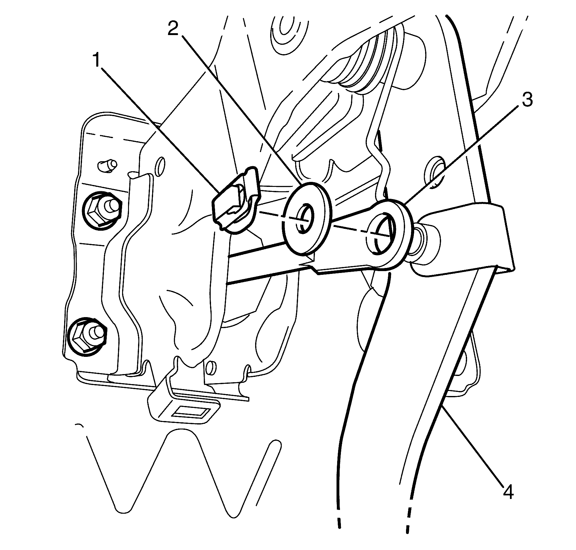
- Remove the brake pedal pushrod retaining clip (1), washer (2) and the brake pedal pushrod (3) from the brake pedal (4).
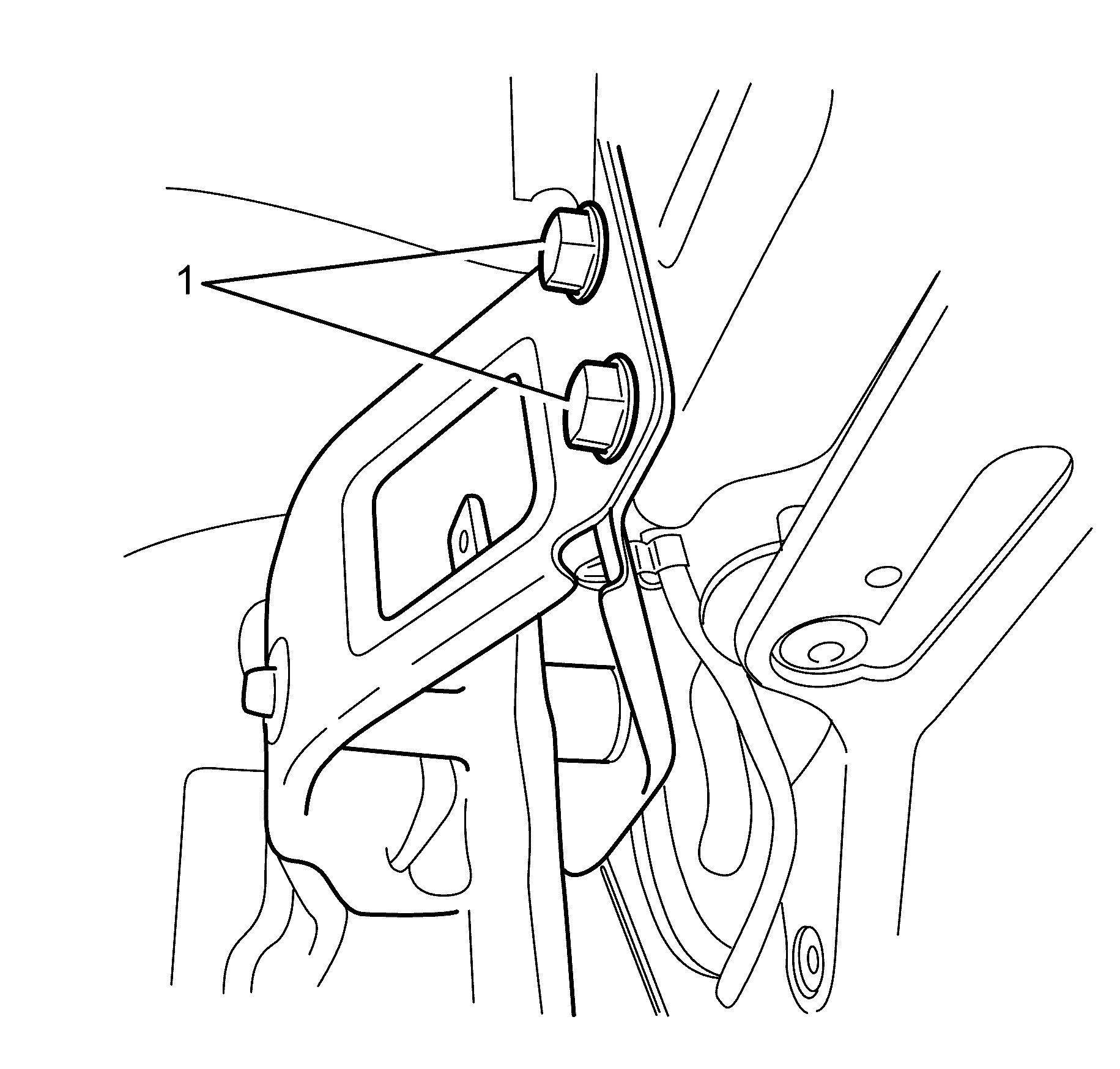
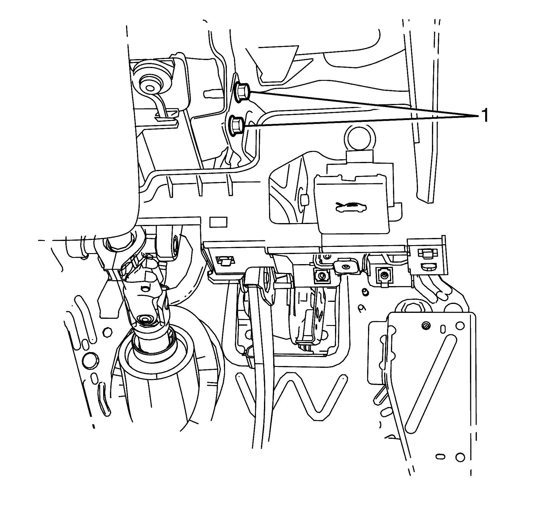
- Remove the vacuum brake booster to brake pedal support bracket retaining nuts (1).
- Remove the vacuum brake booster from the vehicle.
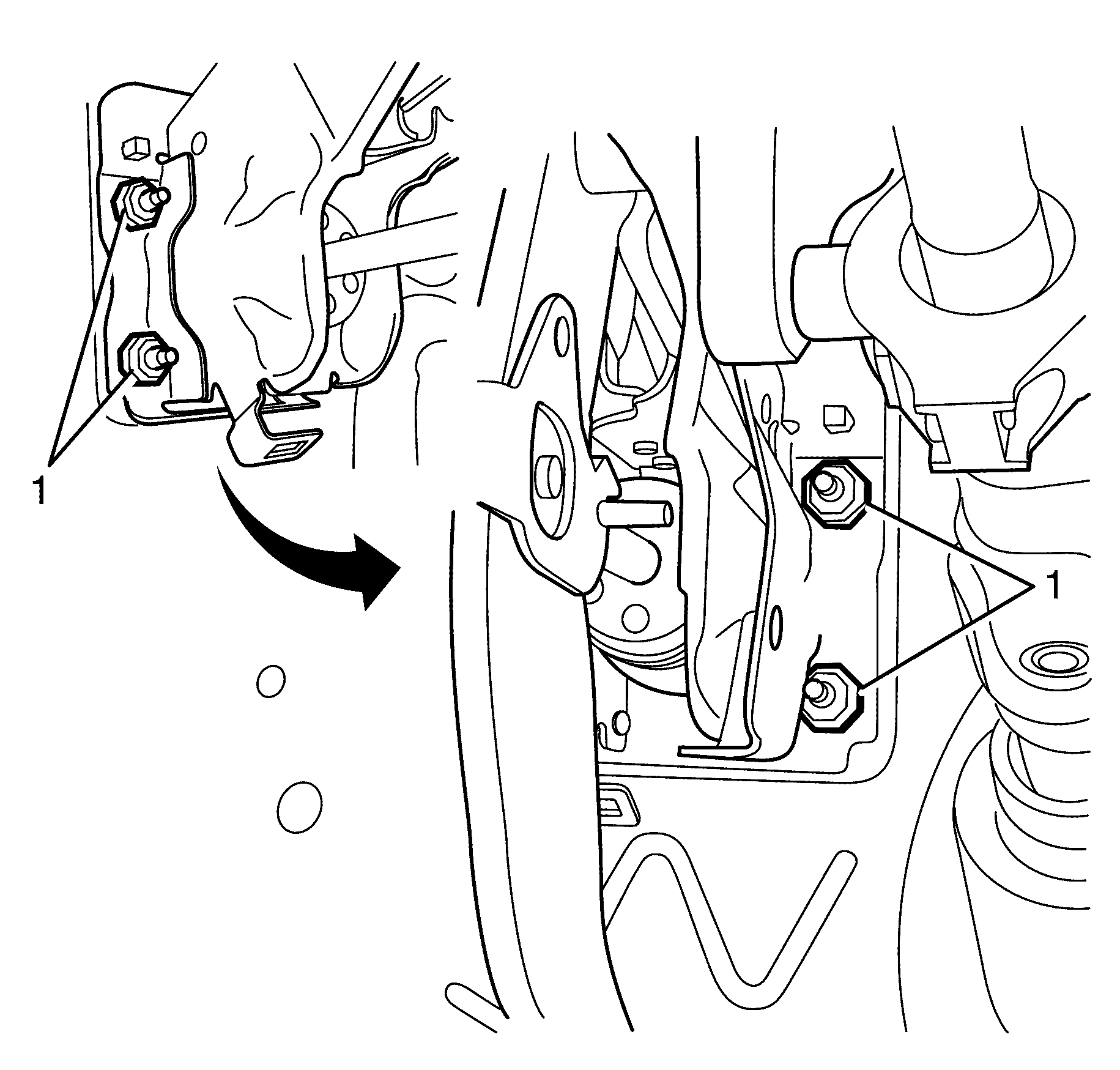
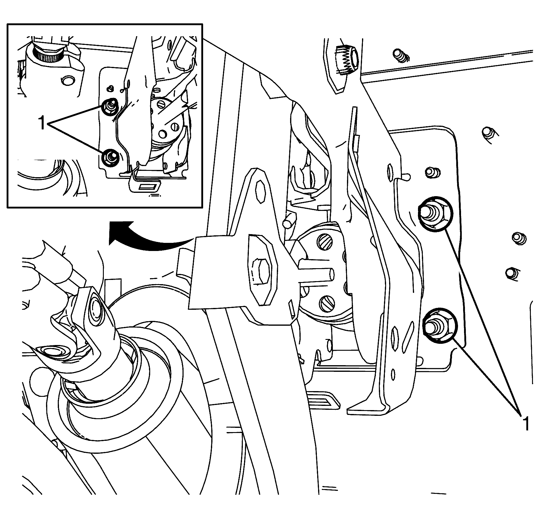
- Remove the two brake pedal bracket assembly to instrument panel crossmember retaining bolts (1).
- Remove the brake pedal assembly from under the instrument panel.
Caution: Refer to Brake Fluid Caution in the Preface section.
Caution: Refer to Brake Fluid Irritant Caution in the Preface section.
Notice: Refer to Adding Fluid to the Brake System Notice in the Preface section.
Notice: Refer to Brake Fluid Effects on Paint and Electrical Components Notice in the Preface section.
Important: From the engine compartment, pull the vacuum brake booster forward to release the four studs from the bulkhead and brake pedal support bracket.
Important: Lower the brake pedal assembly rear end first to aid in removal.
Installation Procedure
- Install the brake pedal assembly.
- Install the two brake pedal bracket assembly to instrument panel crossmember retaining bolts (1).
- Have an assistant install the vacuum brake booster from the engine compartment. Make sure the vacuum brake booster's four studs are correctly located in the bulkhead and brake pedal support bracket.
- Install the push rod (3), washer (2) and retaining clip (1) to the brake pedal assembly (4).
- Install the vacuum brake booster to brake pedal support bracket retaining nuts (1).
- Tighten the two brake pedal bracket assembly to cross car beam retaining bolts (1).
- Install the brake pedal position sensor. Refer to Stop Lamp Switch Replacement.
- Install the vacuum hose and check valve to the vacuum brake booster. Refer to Power Brake Booster Inlet Hose Replacement.
- Install the master cylinder. Refer to Master Cylinder Replacement.
- Bleed the braking system. Refer to Hydraulic Brake System Bleeding.
- Install the instrument panel retainer. Refer to Instrument Panel Retainer Replacement.
- Install the instrument panel insulator panel. Refer to Instrument Panel Insulator Panel Replacement - Left Side.
- Install the instrument panel lower trim panel assembly. Refer to Knee Bolster Replacement.
- Road test the vehicle to inspect correct brake, stop lamp and cruise control operation.
Notice: Refer to Adding Fluid to the Brake System Notice in the Preface section.
Notice: Refer to Brake Fluid Effects on Paint and Electrical Components Notice in the Preface section.
Important: Raise the brake pedal assembly front end first for installation.
DO NOT fully tighten at this stage.
Notice: Refer to Fastener Notice in the Preface section.
Tighten
Tighten the nuts to 22 Nm. (16 lb ft)
Tighten
Tighten the bolts to 23 Nm. (17 lb ft.)
Brake Pedal Assembly Replacement RHD
Removal Procedure
- Remove the instrument panel lower trim panel assembly. Refer to Knee Bolster Replacement.
- Remove the instrument panel lower right trim plate assembly. Refer to Instrument Panel Insulator Panel Replacement - Right Side.
- Remove the instrument panel lower trim panel retainer. Refer to Instrument Panel Retainer Replacement.
- Remove the master cylinder from the vehicle. Refer to Master Cylinder Replacement.
- Remove the vacuum hose and check valve from the vacuum brake booster. Refer to Power Brake Booster Inlet Hose Replacement.
- Remove the brake pedal position sensor. Refer to Stop Lamp Switch Replacement.
- Remove the brake pedal pushrod retaining clip (1), washer (2) and the brake pedal pushrod (3) from the brake pedal (4).
- Remove the vacuum brake booster to brake pedal support bracket retaining nuts (1).
- Remove the vacuum brake booster from the vehicle.
- Remove the two brake pedal bracket assembly to instrument panel crossmember retaining bolts (1).
- Remove the brake pedal assembly from under the instrument panel.
Caution: Refer to Brake Fluid Caution in the Preface section.
Caution: Refer to Brake Fluid Irritant Caution in the Preface section.
Notice: Refer to Adding Fluid to the Brake System Notice in the Preface section.
Notice: Refer to Brake Fluid Effects on Paint and Electrical Components Notice in the Preface section.
Important: From the engine compartment, pull the vacuum brake booster forward to release the four studs from the bulkhead and brake pedal support bracket.
Important: Lower the brake pedal assembly rear end first to aid in removal.
Installation Procedure
- Install the brake pedal assembly to the instrument panel crossmember.
- Install the two brake pedal bracket assembly to instrument panel crossmember retaining bolts (1).
- With the aid of an assistant install the vacuum brake booster from the engine compartment.
- Install the vacuum brake booster to brake pedal support bracket retaining nuts (1).
- Install the push rod (3), washer (2) and retaining clip (1) to the brake pedal assembly (4).
- Tighten the two brake pedal bracket assembly to cross car beam retaining bolts (1).
- Install the brake pedal position sensor. Refer to Stop Lamp Switch Replacement.
- Install the vacuum hose and check valve to the vacuum brake booster. Refer to Power Brake Booster Inlet Hose Replacement.
- Install the master cylinder. Refer to Master Cylinder Replacement.
- Bleed the braking system. Refer to Hydraulic Brake System Bleeding.
- Install the instrument panel lower trim panel retainer. Refer to Instrument Panel Insulator Panel Replacement - Right Side.
- Install the instrument panel lower trim panel assembly. Refer to Knee Bolster Replacement.
- Road test the vehicle to inspect correct brake, stop lamp and cruise control operation.
Caution: Refer to Brake Fluid Caution in the Preface section.
Caution: Refer to Brake Fluid Irritant Caution in the Preface section.
Notice: Refer to Adding Fluid to the Brake System Notice in the Preface section.
Notice: Refer to Brake Fluid Effects on Paint and Electrical Components Notice in the Preface section.
Important: Raise the brake pedal assembly front end first to aid in installation.
DO NOT fully tighten at this stage.
Important: Make sure the vacuum brake booster's four studs are correctly located in the bulkhead and brake pedal support bracket.
Notice: Refer to Fastener Notice in the Preface section.
Tighten
Tighten the nuts to 22 Nm (16 lb ft).
Tighten
Tighten the bolts to 23 Nm (17 lb ft).
