Exhaust Manifold Replacement - Left Side 3.6L Engine LWB SWB
Removal Procedure
- Disconnect the battery ground cable from the battery. Refer to Battery Negative Cable Disconnection and Connection .
- Remove the engine dress cover. Refer to Engine Cover Replacement .
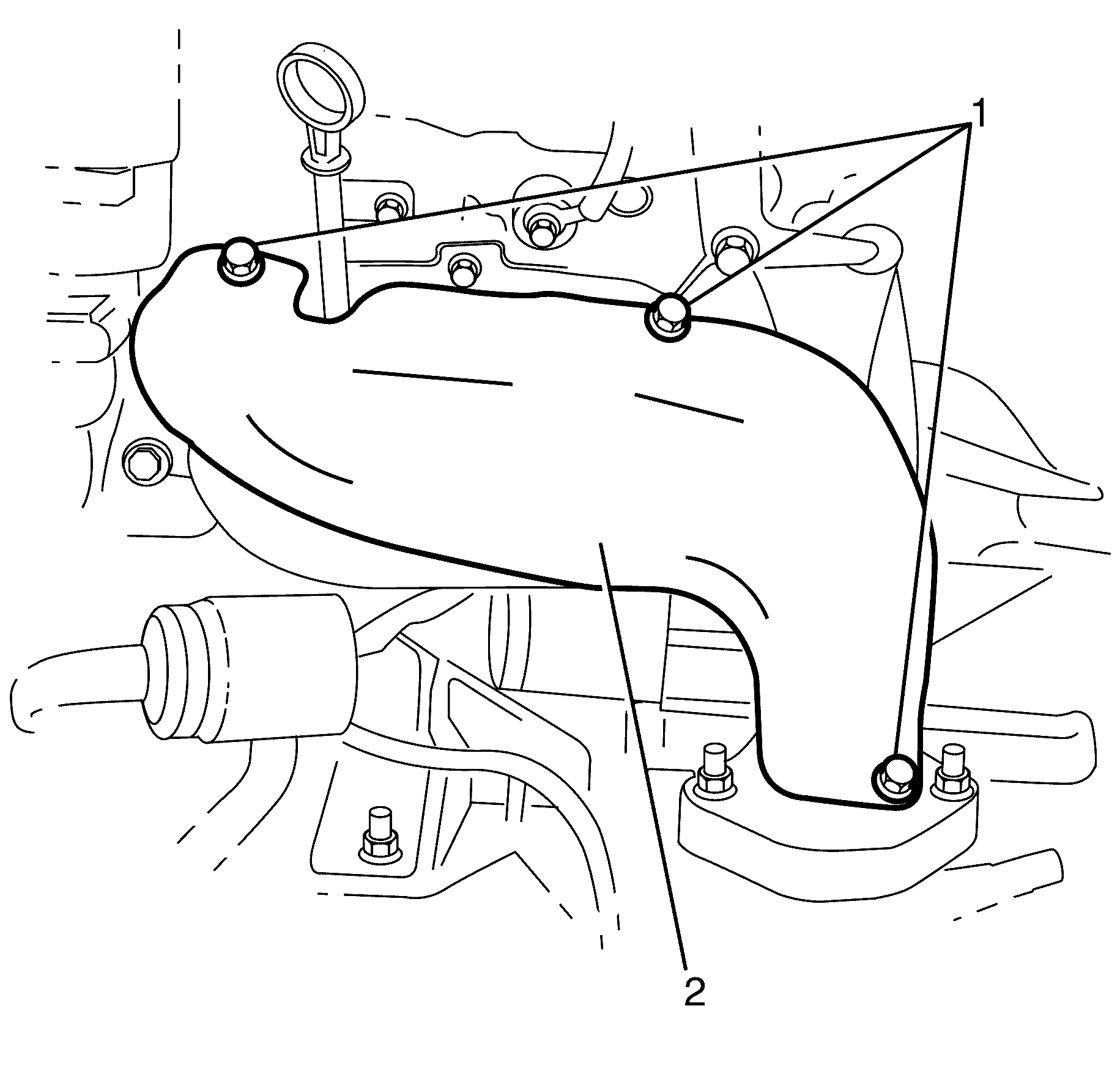
- Remove the exhaust manifold heat shield to exhaust manifold retaining bolts (1).
- Remove the exhaust manifold heat shield (2).
- Remove the oil level indicator tube. Refer to Oil Level Indicator and Tube Removal .
- Remove the left catalytic converter to exhaust manifold retaining nuts (2).
- Raise and support the vehicle. Refer to Lifting and Jacking the Vehicle .
- Remove the left catalytic converter. Refer to Catalytic Converter Replacement - Left Side .
- Remove the starter motor. Refer to Starter Motor Replacement .
- Lower the vehicle.
- Loosen the exhaust manifold to cylinder head retaining bolts (1) working from the outside to the centre.
- Remove the exhaust manifold to cylinder head retaining bolts (1).
- Raise and support the vehicle. Refer to Lifting and Jacking the Vehicle .
- Remove the exhaust manifold (2).
Caution: Refer to Exhaust Service Caution in the Preface section.
Caution: Refer to Protective Goggles and Glove Caution in the Preface section.
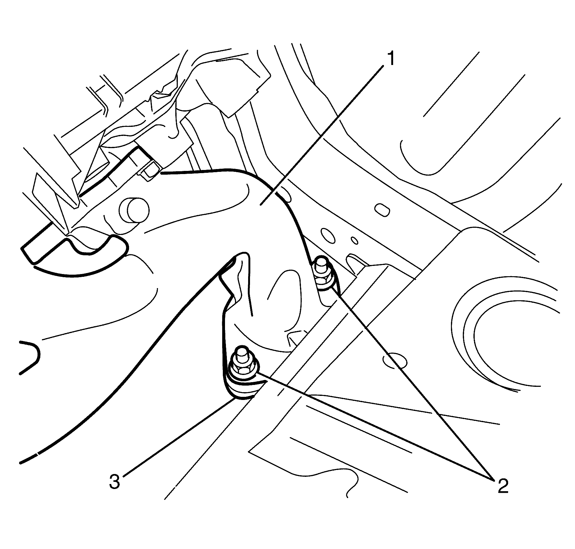
Important: The left catalytic converter to exhaust manifold retaining nuts (2) are single use parts. They must be discarded after removal.
Discard the nuts.
Caution: Refer to Vehicle Lifting Caution in the Preface section.
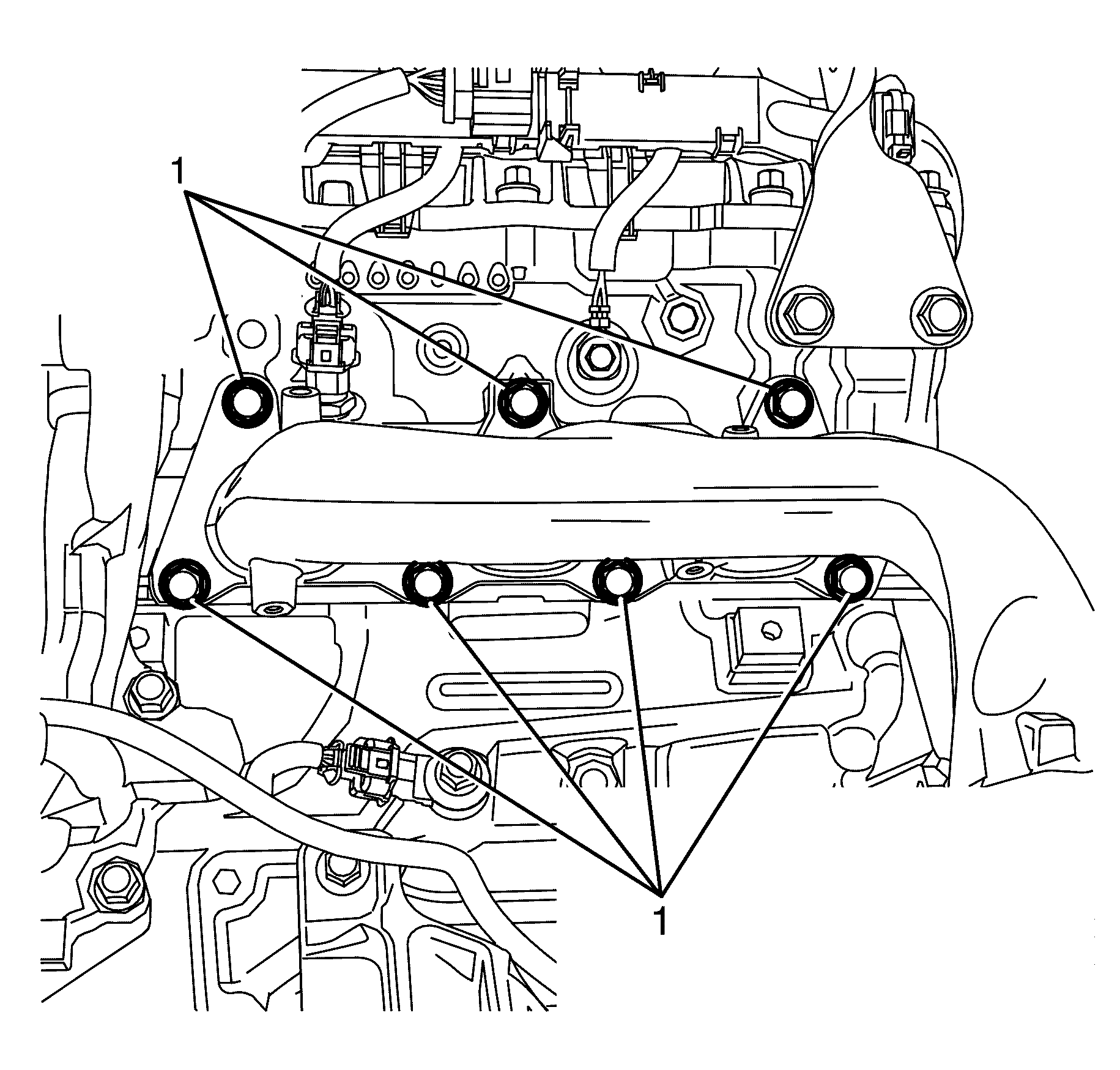
Important: Bolts with micro-encapsulated thread sealant must be discarded after removal.
Discard the bolts.
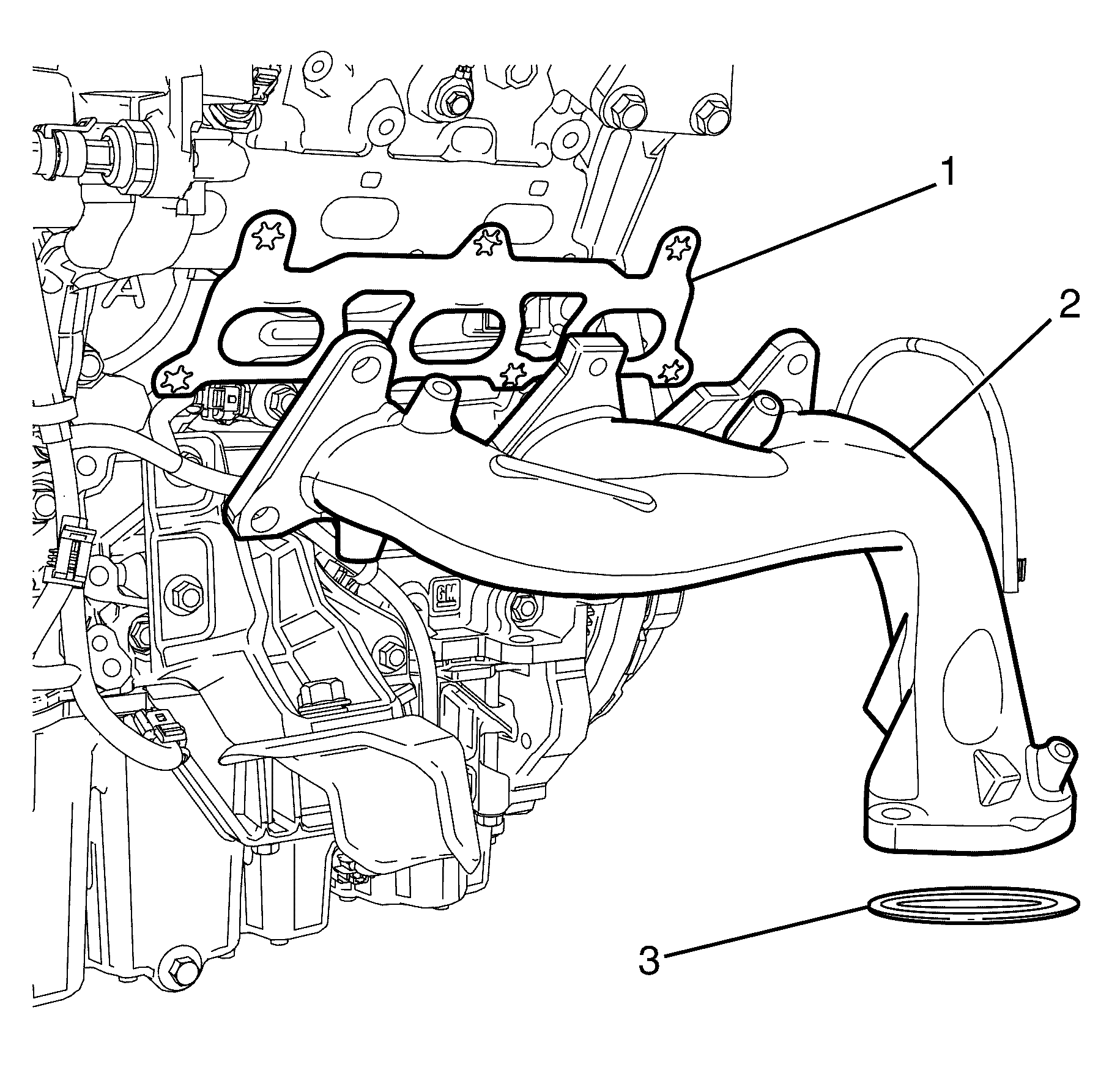
Important: Make sure that the surrounding wiring harness and electrical connectors are not damaged when removing the exhaust manifold (2).
Important: The exhaust manifold gasket (1) and sealing ring (3) are single use parts. They must be discarded after removal.
Discard the exhaust manifold gasket (1) and sealing ring (3).
Installation Procedure
- Before installation inspect for the following:
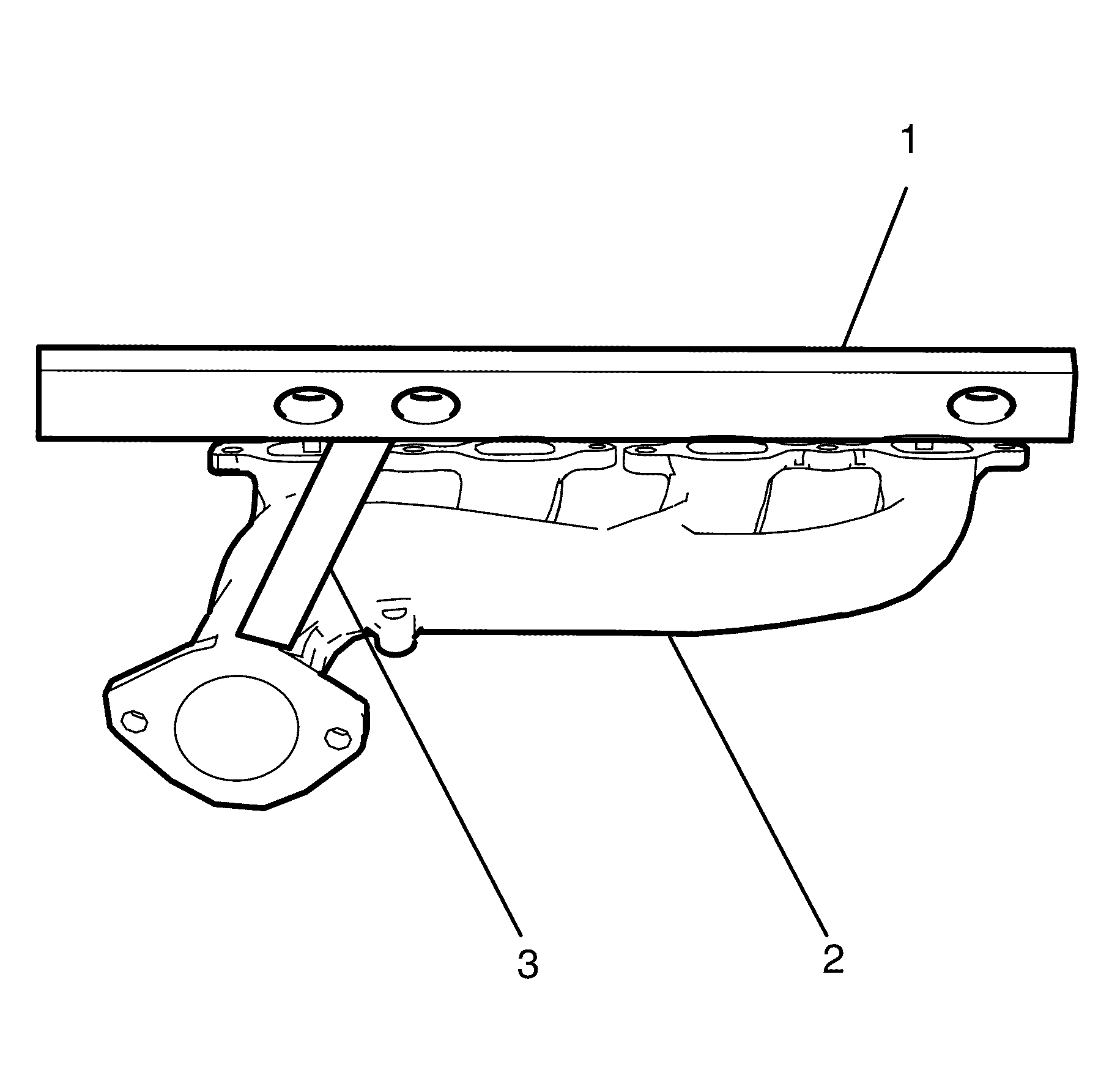
- Check for distortion on the mating surface of the exhaust manifold (2) by using a straight edge (1) and a feeler gauge (3).
- Clean the exhaust manifold and catalytic converter flange mating surfaces.
- Install a NEW exhaust manifold gasket (1) and NEW sealing ring (3) to the exhaust manifold (2).
- Install the exhaust manifold assembly to the engine.
- Lower the vehicle.
- Install the NEW exhaust manifold to cylinder head retaining bolts (1).
- Install the left catalytic converter. Refer to Catalytic Converter Replacement - Left Side .
- Install the starter motor. Refer to Starter Motor Replacement .
- Install the NEW left catalytic converter to exhaust manifold retaining nuts (2).
- Tighten the exhaust manifold to cylinder head retaining bolts (1) working from the centre to the outside.
- Install the exhaust manifold heat shield (2).
- Install the exhaust manifold heat shield to exhaust manifold retaining bolts (1).
- Install the engine dress cover. Refer to Engine Cover Replacement .
- Connect the battery ground cable to the battery. Refer to Battery Negative Cable Disconnection and Connection .
Notice: Refer to Exhaust Service Caution in the Preface section.
| • | Damage to the gasket sealing surfaces. |
| • | Distortion of exhaust manifold mating surface. |
| • | Damage to the exhaust mounting holes. |
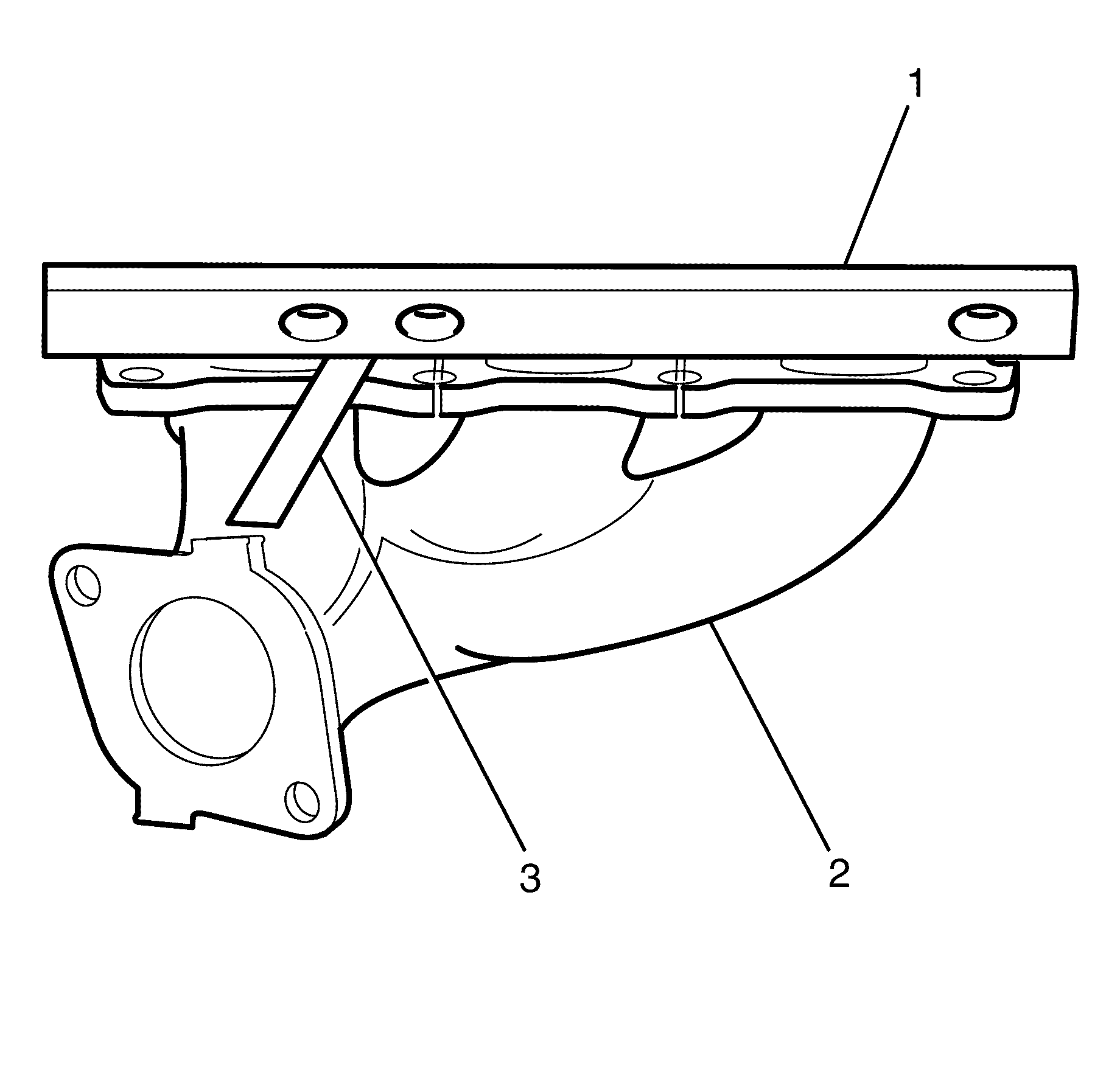

Notice: Refer to Exhaust System Inspection Notice in the Preface section.

Important: Do not fully tighten the exhaust manifold to cylinder head retaining bolts (1) at this stage.
Do not fully tighten at this stage.

Important: Make sure the sealing ring is seated correctly.
Notice: Refer to Fastener Notice in the Preface section.
Tighten
Tighten the nuts to 45 N·m (33 lb ft).

Tighten
Tighten the bolts to 20 N·m (15 lb ft).

Tighten
Tighten the bolts to 10 N·m (89 lb in).
Exhaust Manifold Replacement - Left Side 6.0L Engine LWB SWB
Removal Procedure
- Disconnect the battery ground cable from the battery. Refer to Battery Negative Cable Disconnection and Connection .
- Remove the engine dress cover. Refer to Engine Cover Replacement .
- Remove the air cleaner assembly. Refer to Air Cleaner Assembly Replacement .
- Remove the left side spark plug leads. Refer to Spark Plug Wire Replacement .
- Remove the left side spark plugs from the cylinder head. Refer to Spark Plug Replacement .
- Remove the exhaust manifold heat shield to exhaust manifold retaining bolts (2).
- Remove the exhaust manifold heat shield (1).
- Remove the engine coolant temperature sensor. Refer to Engine Coolant Temperature Sensor Replacement .
- Remove the left catalytic converter to exhaust manifold retaining nuts (2).
- Disconnect the left catalytic converter (3) from the exhaust manifold (4).
- Loosen the exhaust manifold to cylinder head retaining bolts (1) working from the outside to the centre.
- Remove the exhaust manifold to cylinder head retaining bolts (1).
- Remove the exhaust manifold (2).
Caution: Refer to Exhaust Service Caution in the Preface section.
Caution: Refer to Protective Goggles and Glove Caution in the Preface section.
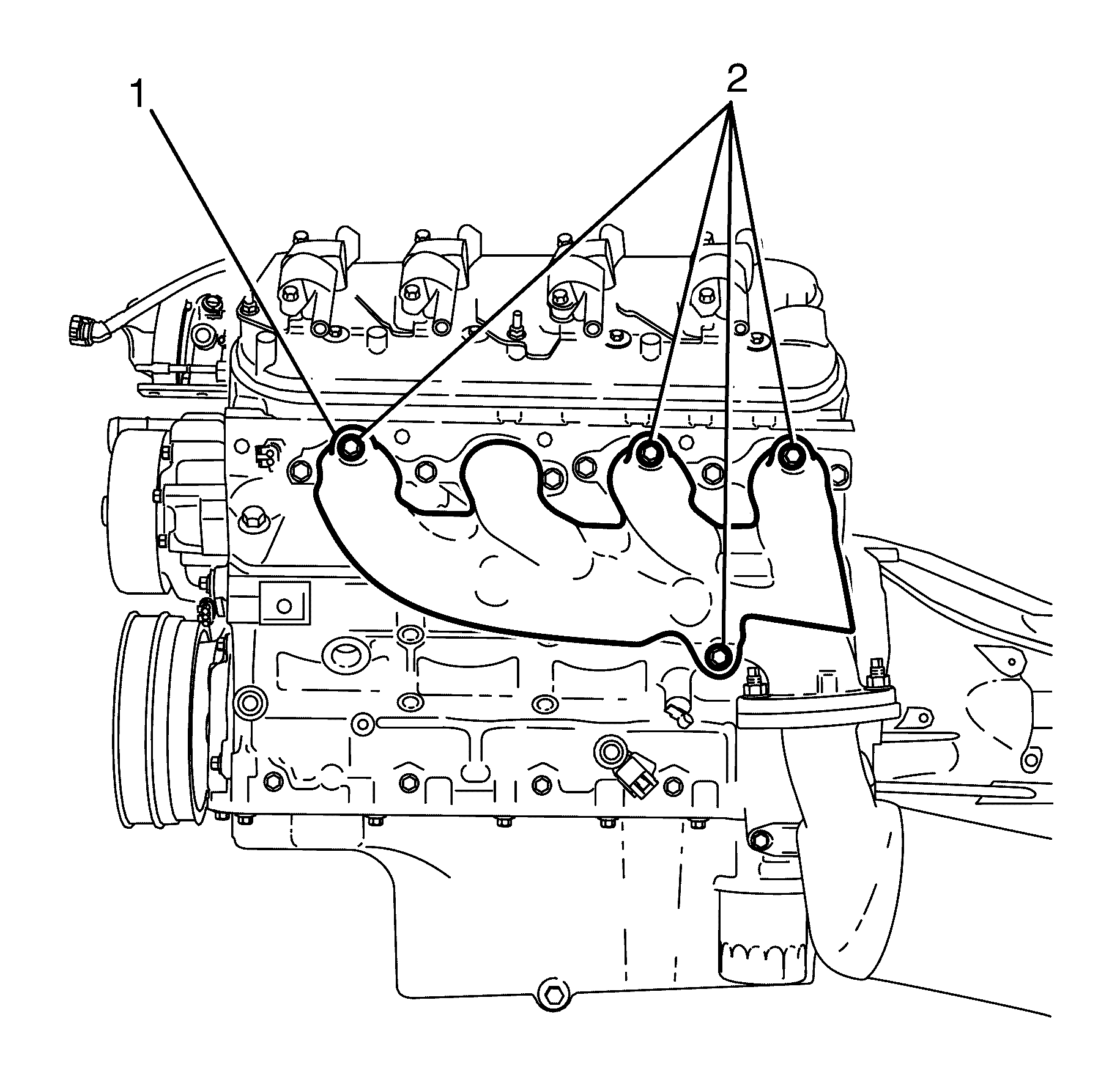
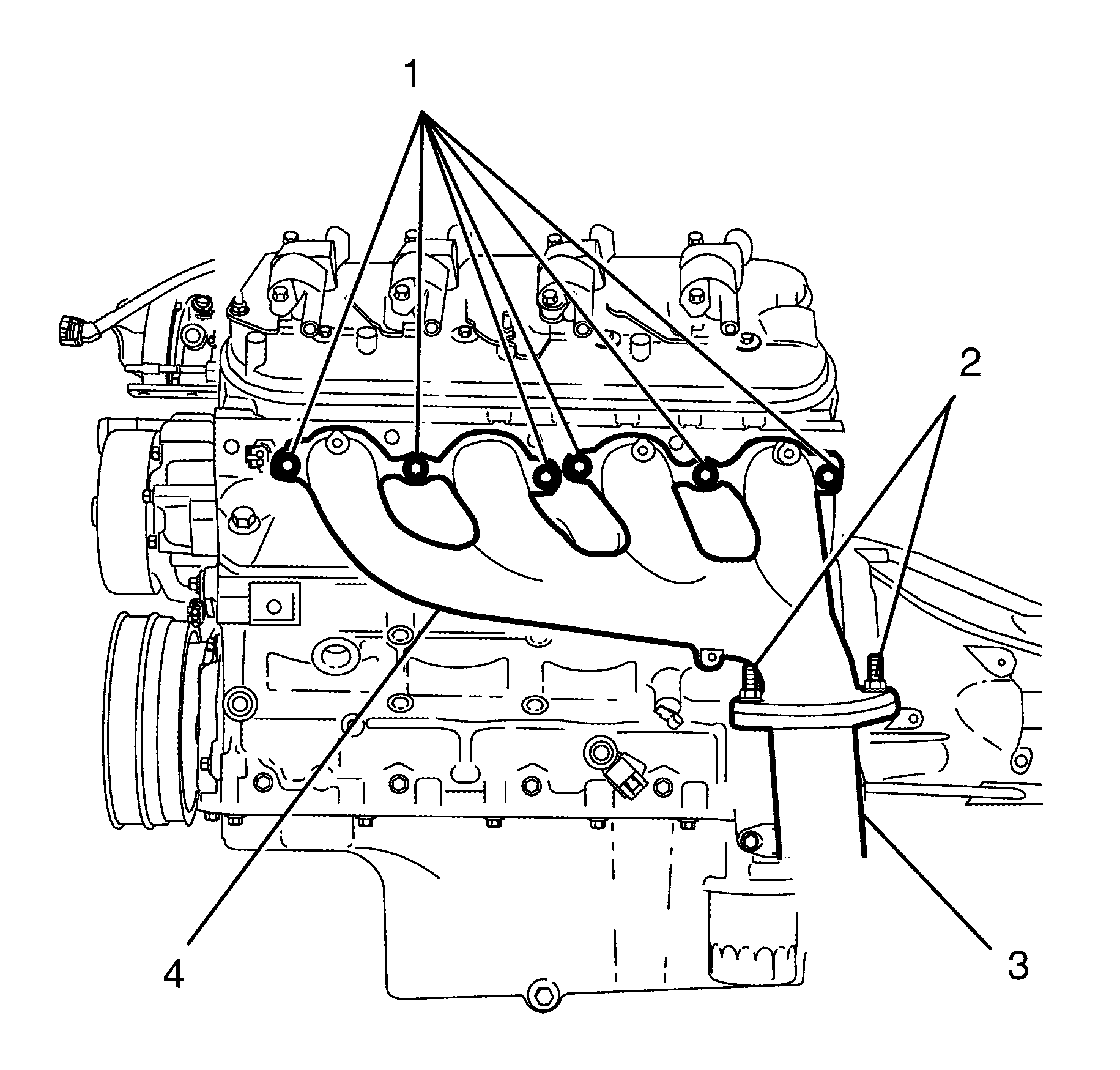
Important: The left catalytic converter to exhaust manifold retaining nuts (2) are single use parts. They must be discarded after removal.
Discard the nuts.
Important: Bolts with micro-encapsulated thread sealant must be discarded after removal.
Discard the bolts.
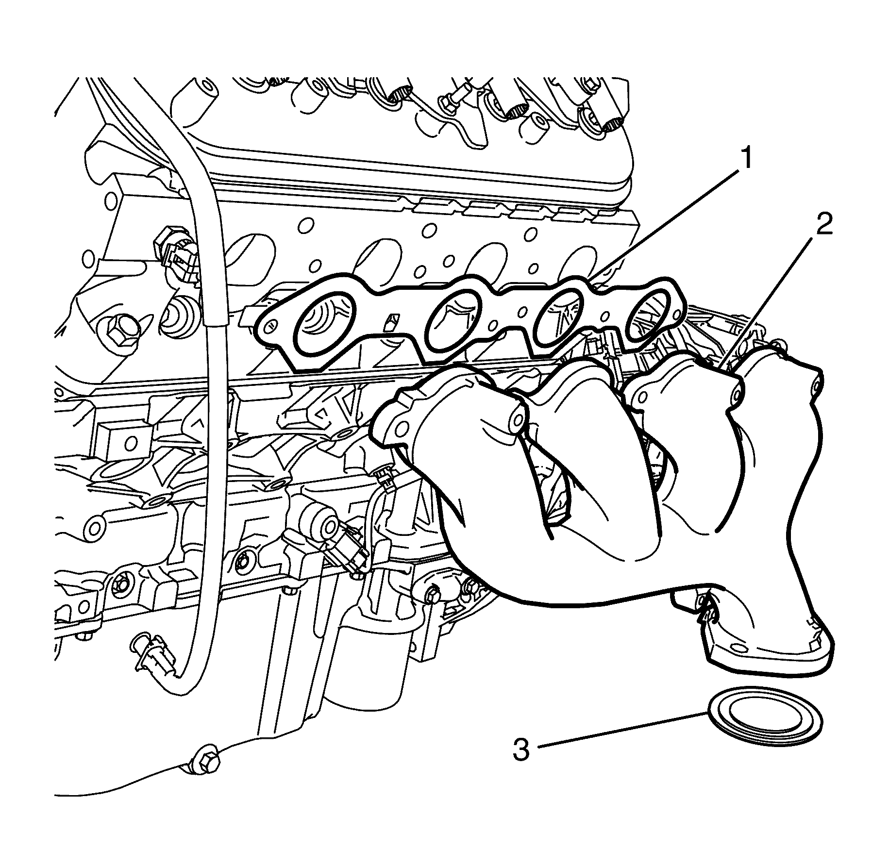
Important: Make sure that the surrounding wiring harness and electrical connectors are not damaged when removing the exhaust manifold (2).
Important: The exhaust manifold gasket (1) and sealing ring (3) are single use parts. They must be discarded after removal.
Discard the exhaust manifold gasket (1) and sealing ring (3).
Installation Procedure
Inspect
- Before installation inspect for the following:
- Check for distortion on the mating surface of the exhaust manifold (3) by using a straight edge (1) and a feeler gauge (2).
- Clean the exhaust manifold and catalytic converter flange mating surfaces.
- Install a NEW exhaust manifold gasket (1) and NEW sealing ring (3) to the exhaust manifold (2).
- Install the exhaust manifold assembly to the engine.
- Install the NEW exhaust manifold to cylinder head retaining bolts (1).
- Lift the left catalytic converter (3) up and forward to connect to the exhaust manifold (4).
- Clean the threads of the exhaust manifold to catalytic converter retaining studs with a suitable cleaning solvent.
- Install the NEW left catalytic converter to exhaust manifold retaining nuts (2).
- Tighten the exhaust manifold to cylinder head retaining bolts (1) working from the centre to the outside.
- Install the engine coolant temperature sensor. Refer to Engine Coolant Temperature Sensor Replacement .
- Install the exhaust manifold heat shield (1).
- Install the exhaust manifold heat shield to exhaust manifold retaining bolts (2).
- Install the left side spark plugs to the cylinder head. Refer to Spark Plug Replacement .
- Install the left side spark plug leads. Refer to Spark Plug Wire Replacement .
- Install the air intake duct. Refer to Air Cleaner Assembly Replacement .
- Install the engine dress cover. Refer to Engine Cover Replacement .
- Connect the battery ground cable to the battery. Refer to Battery Negative Cable Disconnection and Connection .
Notice: Refer to Exhaust Service Caution in the Preface section.
| • | Damage to the gasket sealing surfaces. |
| • | Distortion of exhaust manifold mating surface. |
| • | Damage to the exhaust mounting holes. |

Notice: Refer to Exhaust System Inspection Notice in the Preface section.

Important: Do not fully tighten the exhaust manifold to cylinder head retaining bolts (1) at this stage.
Do not fully tighten at this stage.
Important: Make sure the sealing ring is seated correctly.
Notice: Refer to Fastener Notice in the Preface section.
Tighten
Tighten the nuts to 45 N·m (33 lb ft).
Tighten
Tighten the bolts to 20 N·m (15 lb ft).

Tighten
Tighten the bolts to 10 N·m (89 lb in).
Exhaust Manifold Replacement - Left Side 6.0L Engine CSV HSV VXR8
Removal Procedure -- LS2
- Disconnect the battery ground cable from the battery. Refer to Battery Negative Cable Disconnection and Connection.
- Remove the engine dress cover. Refer to Engine Cover Replacement.
- Remove the air cleaner assembly. Refer to Air Cleaner Assembly Replacement.
- Remove the left side spark plug leads. Refer to Spark Plug Wire Replacement.
- Remove the left side spark plugs from the cylinder head. Refer to Spark Plug Replacement.
- Remove the left side catalytic converter. Refer to Catalytic Converter Replacement - Left Side.
- Remove the engine coolant temperature sensor. Refer to Engine Coolant Temperature Sensor Replacement.
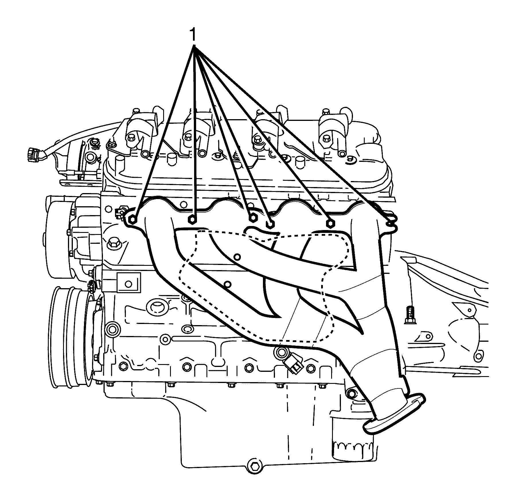
- Loosen the exhaust manifold to cylinder head retaining bolts (1) working from the outside to the centre.
- Remove the exhaust manifold to cylinder head retaining bolts (1).
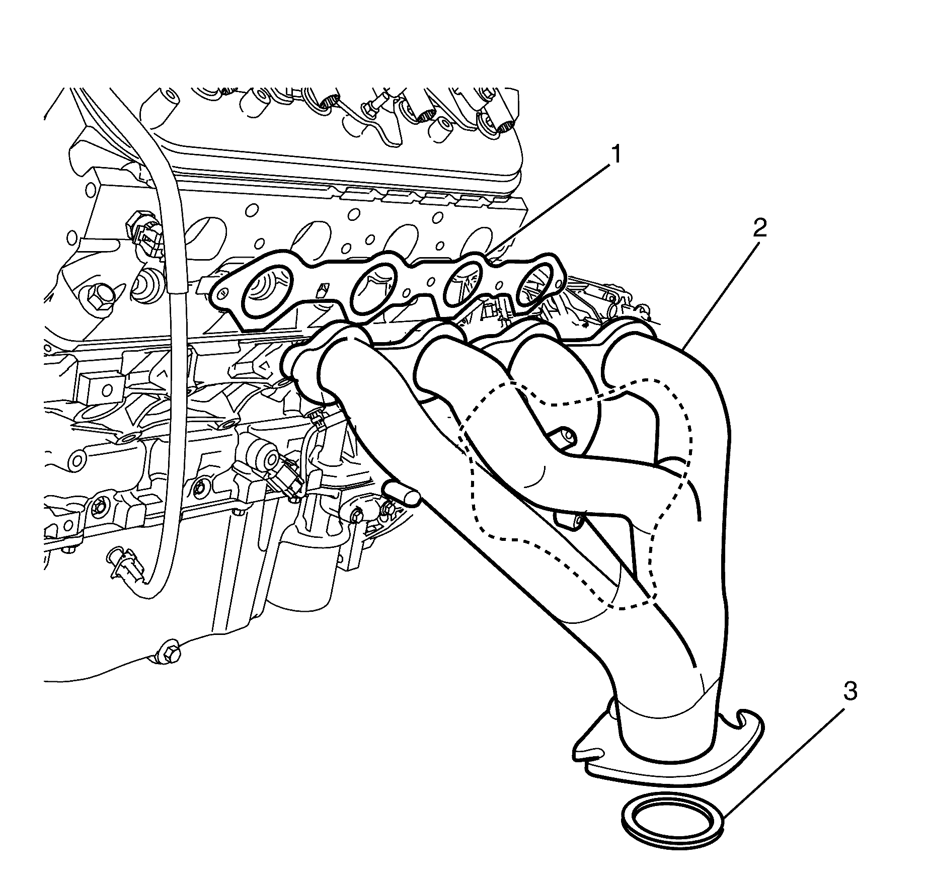
- Remove the exhaust manifold (2).
Caution: Refer to Exhaust Service Caution in the Preface section.
Caution: Refer to Protective Goggles and Glove Caution in the Preface section.
Important: Bolts with micro-encapsulated thread sealant must be discarded after removal.
Discard the bolts.
Important: Make sure that the surrounding wiring harness and electrical connectors are not damaged when removing the exhaust manifold (2).
Important: The exhaust manifold gasket (1) and sealing ring (3) are single use parts. They must be discarded after removal.
Important: The left hand exhaust manifold can only be removed from underneath the vehicle.
Discard the exhaust manifold gasket (1) and sealing ring (3).
Installation Procedure -- LS2
Inspect
- Before installation inspect for the following:
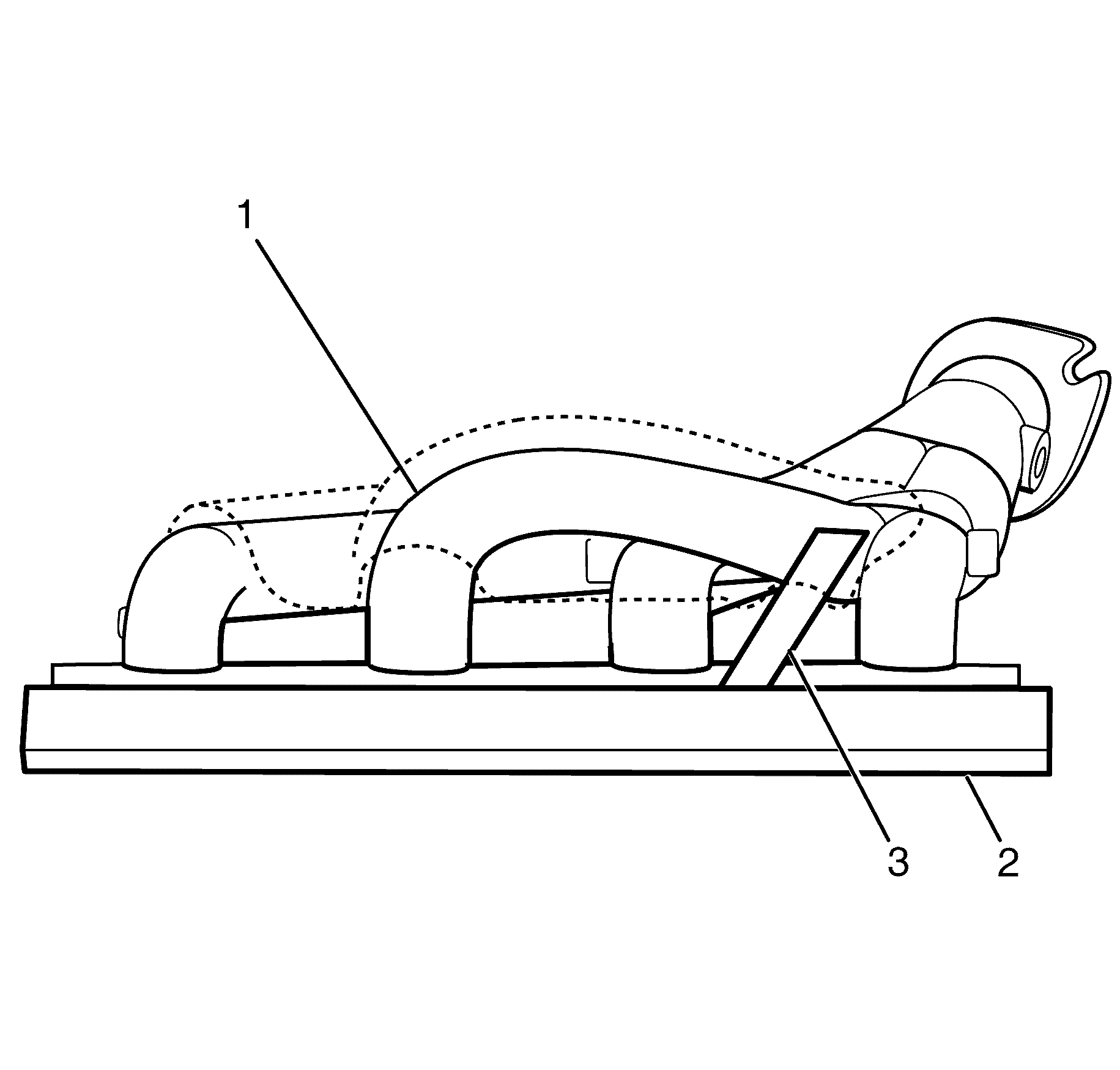
- Check for distortion on the mating surface of the exhaust manifold (1) by using a straight edge (2) and a feeler gauge (3).
- Clean the exhaust manifold and catalytic converter flange mating surfaces.
- Install a NEW exhaust manifold gasket (1) and NEW sealing ring (3) to the exhaust manifold (2).
- Install the exhaust manifold assembly (2) to the engine.
- Install the NEW exhaust manifold to cylinder head retaining bolts (1).
- Clean the threads of the exhaust manifold to catalytic converter retaining studs with a suitable cleaning solvent.
- Install the left side catalytic converter. Refer to Catalytic Converter Replacement - Left Side.
- Tighten the exhaust manifold to cylinder head retaining bolts (1) working from the centre to the outside.
- Install the engine coolant temperature sensor. Refer to Engine Coolant Temperature Sensor Replacement.
- Install the left side spark plugs to the cylinder head. Refer to Spark Plug Replacement.
- Install the left side spark plug leads. Refer to Spark Plug Wire Replacement.
- Install the air cleaner assembly. Refer to Air Cleaner Assembly Replacement.
- Perform diagnostic system check using diagnostic scan tool, clear all relative DTC's and inspect the system for correct operation.
- Install the engine dress cover. Refer to Engine Cover Replacement.
- Connect the battery ground cable to the battery. Refer to Battery Negative Cable Disconnection and Connection.
Notice: Refer to Exhaust Service Caution in the Preface section.
| • | Damage to the gasket sealing surfaces. |
| • | Distortion of exhaust manifold mating surface. |
| • | Damage to the exhaust mounting holes. |

Notice: Refer to Exhaust System Inspection Notice in the Preface section.

Important: Do not fully tighten the exhaust manifold to cylinder head retaining bolts (1) at this stage.
Do not fully tighten at this stage.
Important: Make sure the sealing ring is seated correctly.
Tighten
Tighten the bolts to 20 Nm (15 lb ft).
