SERVICE MANUAL REVISION IDLE LOAD COMPENSATOR

Model and Year: 1986-87 CAPRICE WAGON
The attached information replaced the 1986 and 1987 Service Manual information published in the service manuals.
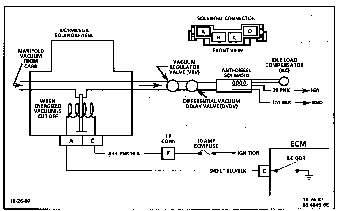
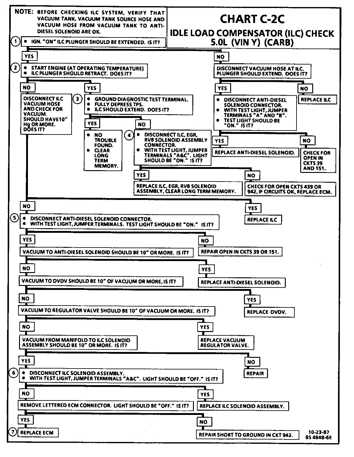
The chart C-2C has been changed to show all the components between the ILC/RVB/EGR solenoid assembly and idle load compensator. The C-2C diagnostic chart has been reworked to more thoroughly diagnose any failure of components within the ILC vacuum and electrical system.
Please replace the original charts with the ones supplied in this bulletin.
CHART C-2C IDLE LOAD COMPENSATOR (ILC) CHECK 5.OL (VIN Y) (CARB)
Circuit Description:
The idle load compensator (ILC) is mounted on the carburetor and is used to control various low engine rpm conditions. The ILC uses a spring loaded vacuum sensitive diaphragm whose plunger extends when vacuum is not present. Vacuum to the ILC is controlled by the ECM through the ILC/RVB/EGR solenoid assembly. When the ECM turns "ON" the ILC solenoid assembly, vacuum is cut "OFF" to the ILC. Vacuum is regulated through the VRV and delayed under high load conditions (checked) by the DVDV and through the Anti-diesel solenoid (ADS). The ADS is energized when the IGN is turned "ON", allowing vacuum to the ILC, and turned "OFF" when the IGN is "OFF." This supplies vacuum to the ILC, keeping the plunger retracted so the engine can shut down without dieseling.
Test Description:
Numbers below refer to circled numbers on the diagnostic chart.
1. ILC plunger should be extended as no vacuum is being applied.
2. ILC plunger should retract if vacuum is applied.
3. Depressing the TPS should make the ECM turn the ILC quad-driver "ON," blocking vacuum to the ILC, and simulating a W.O.T. condition. Clear long term memory after this procedure, as the ECM must relearn correct TPS voltage.
4. With test terminal grounded, ECM should be turning " ON" ILC solenoid assembly. Test light should be "ON."
5. Anti-diesel solenoid is energized any time ignition is "ON," so test light should be "ON."
6. Test light should be "OFF," as ILC quad-driver should be turned "OFF."
7. If the test light goes out, the ECM has to be replaced, as the quad-driver inside the ECM has failed.


General Motors bulletins are intended for use by professional technicians, not a "do-it-yourselfer". They are written to inform those technicians of conditions that may occur on some vehicles, or to provide information that could assist in the proper service of a vehicle. Properly trained technicians have the equipment, tools, safety instructions and know-how to do a job properly and safely. If a condition is described, do not assume that the bulletin applies to your vehicle, or that your vehicle will have that condition. See a General Motors dealer servicing your brand of General Motors vehicle for information on whether your vehicle may benefit from the information.
