Circuit Description
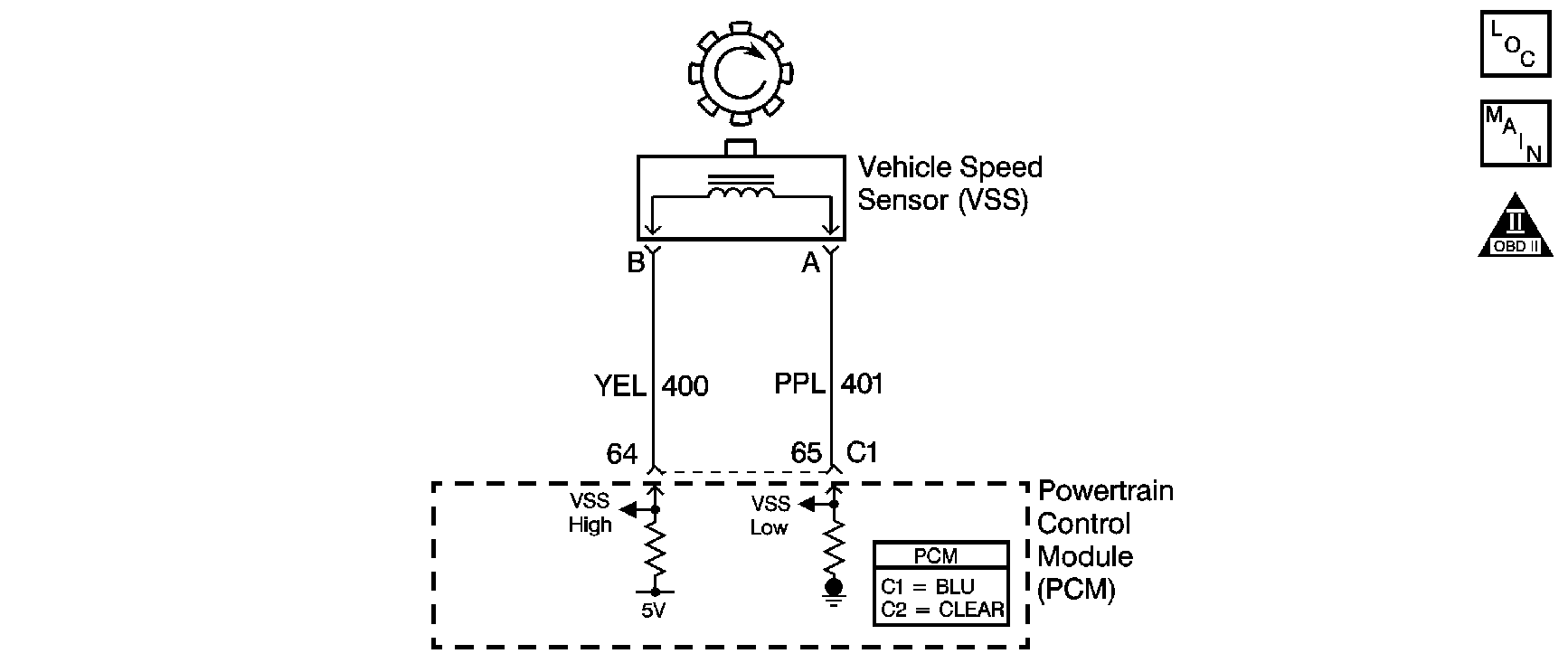
Vehicle speed information is provided to the powertrain control module (PCM) by the vehicle speed sensor (VSS). The VSS consists of a magnetic pickup sensor mounted to the transmission case which interfaces with a rotor pressed onto to the transmission output shaft. The VSS produces a frequency signal that is proportional to vehicle speed. The PCM converts the VSS signal to vehicle speed, displayed on the scan tool in miles per hour and kilometers per hour. The PCM also uses the VSS signal to generate the 4,000 pulses per mile vehicle speed signal used by the instrument cluster.
Conditions for Running the DTC
| • | Engine speed is more than 1,250 RPM. |
| • | Engine load and engine speed acceleration indicate that the vehicle is in gear. |
Conditions for Setting the DTC
The vehicle speed sensor indicates a speed of less than 5 km/h (3 mph) for more than 20 seconds.
Action Taken When the DTC Sets
| • | The PCM illuminates the malfunction indicator lamp (MIL) on the second consecutive ignition cycle that the diagnostic runs and fails. |
| • | The PCM disables Cruise Control. |
| • | The PCM records the operating conditions at the time when the Conditions for Setting the DTC are met. The PCM stores this information as Freeze Frame and Failure Records. |
| • | The PCM stores P0500 in PCM history. |
Conditions for Clearing the MIL/DTC
| • | The PCM turns OFF the MIL during the third consecutive trip in which the diagnostic runs and passes. |
| • | The PCM cancels the DTC default actions when the ignition switch is OFF long enough in order to power down the PCM. |
| • | The PCM clears the DTC from PCM history if the vehicle completes 40 warm-up cycles without an emission-related diagnostic fault occurring. |
| • | A scan tool can clear the MIL/DTC. |
Diagnostic Aids
Ensure the VSS is correctly torqued to the transmission housing.
Test Description
The numbers below refer to the step numbers on the diagnostic table.
-
The resistance measurement will not change if either the VSS high signal circuit or the VSS low signal circuit, but not both, is shorted to ground. The vehicle speed detector in the PCM and the VSS are matched in such a way that an open or a short to ground in the VSS low signal circuit will not usually cause a loss of speed signal or a DTC P0500 to set. The lower resistance value given represents the nominal resistance specification of the VSS at -40°C (-40°F), minus the manufacturing tolerance specification of 10 percent. The higher resistance value given represents the nominal resistance specification of the VSS at 150°C (302°F), plus the manufacturing tolerance specification of 10 percent.
-
This step isolates the short between the VSS and the wiring.
-
Do not skip Step 7. The DMM will detect AC voltage if the VSS high signal circuit is shorted to ground.
-
The replacement PCM must be programmed and the crankshaft position system variation procedure must be performed. Refer to the latest Techline procedures for PCM reprogramming.
Step | Action | Value(s) | Yes | No | ||||||||
|---|---|---|---|---|---|---|---|---|---|---|---|---|
1 | Did you perform the Diagnostic System Check - Manual Transmission ? | -- | Go to Step 2 | |||||||||
2 |
Notice: In order to avoid damage to the drive axles, support the lower control arms in the normal horizontal position. Do not run the vehicle in gear with the wheels hanging down at full travel. Important: Record the Failure Records before clearing the DTCs. Using the Clear Info function erases the Failure Records from the PCM. Does the scan tool display vehicle speed above the specified value? | 0 km/h (0 mph) | Go to Step 3 | Go to Step 4 | ||||||||
3 |
Does the scan tool display vehicle speed above the specified value? | 0 km/h (0 mph) | Go to Intermittent Conditions in Engine Controls - 3.8 L | Go to Step 4 | ||||||||
4 |
Did the PCM require a calibration update? | -- | Go to Step 14 | Go to Step 5 | ||||||||
Is the resistance within the specified range? | 1668-2913 ohms | Go to Step 7 | Go to Step 6 | |||||||||
6 | Test the VSS high signal and VSS low signal circuits for the following conditions:
Refer to Circuit Testing in Wiring Systems. Did you find and correct a condition? | -- | Go to Step 14 | Go to Step 11 | ||||||||
7 | Measure the resistance between the terminal C1 64 and ground. Is the resistance greater than the specified value? | 50 K ohms | Go to Step 10 | Go to Step 8 | ||||||||
Is the resistance greater than the specified value? | 50 K ohms | Go to Step 11 | Go to Step 9 | |||||||||
9 | Repair the short to ground in the VSS high signal circuit. Did you complete the repair? | -- | Go to Step 14 | -- | ||||||||
Is the AC voltage equal to or greater than the specified value? | 0.5 V | Go to Step 14 | Go to Step 11 | |||||||||
11 |
Did you find and correct a condition? | -- | Go to Step 14 | Go to Step 12 | ||||||||
12 | Replace the VSS. Refer to Vehicle Speed Sensor Replacement . Did you complete the repair? | -- | Go to Step 14 | -- | ||||||||
Replace the PCM. Refer to Powertrain Control Module Replacement in Engine Controls - 3.8 L. Is the action complete? | -- | Go to Step 14 | -- | |||||||||
14 |
Does the scan tool indicate that this diagnostic has run and passed? | -- | System OK | Go to Step 2 |
