Refer to Engine Controls Schematics,
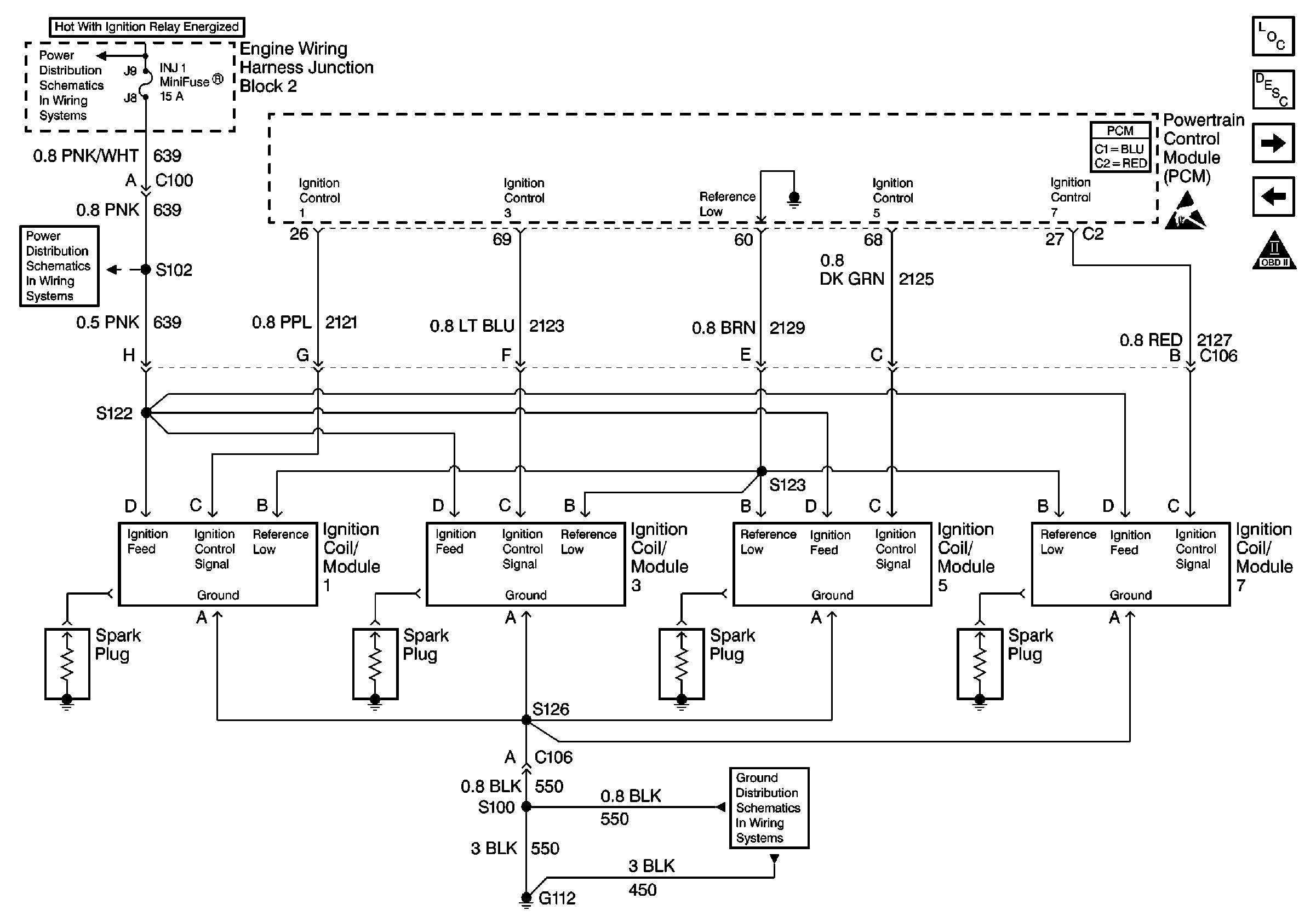
Ignition Modules/Coils, Bank 1
or
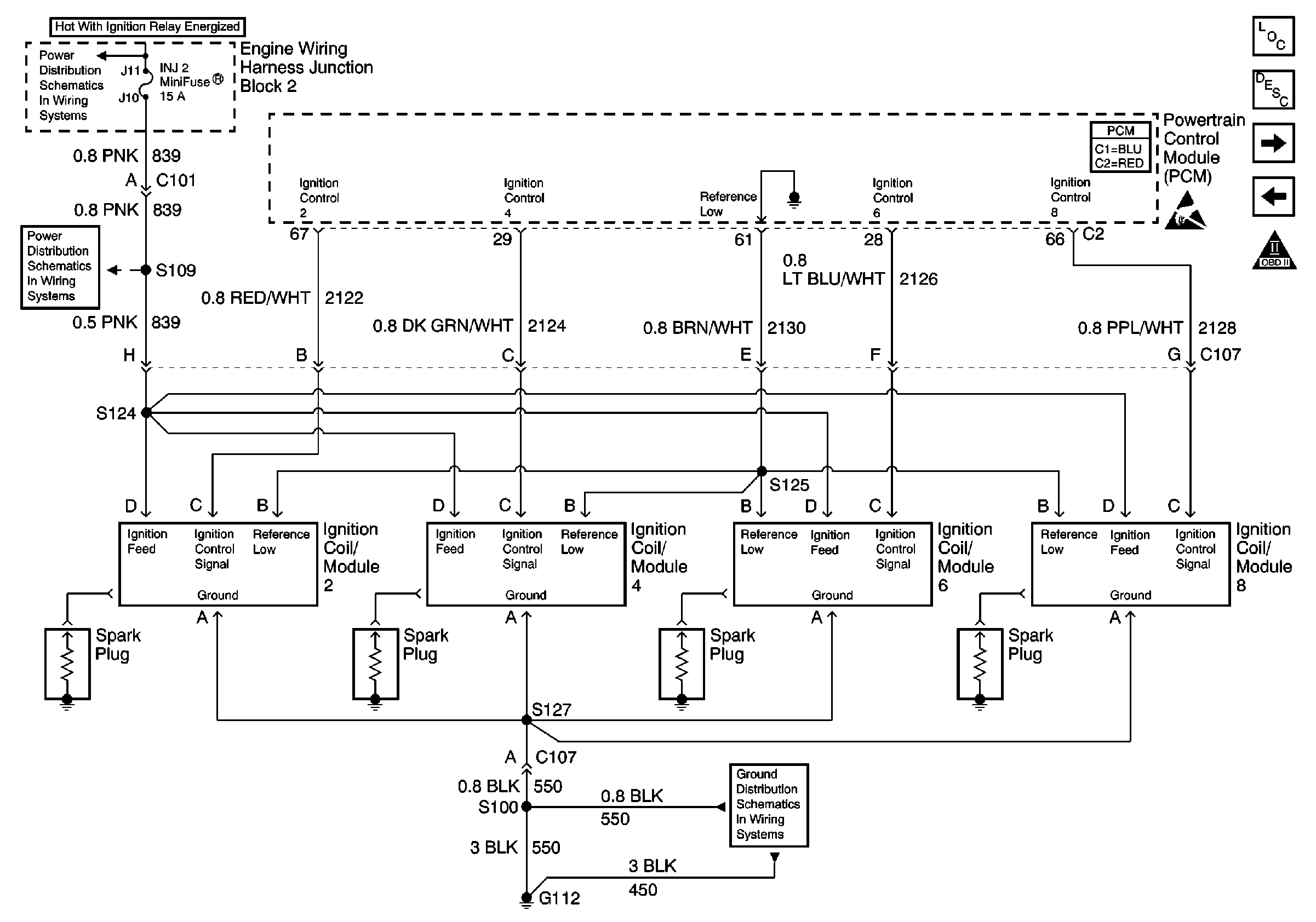
Ignition Modules/Coils, Bank 2
for complete
circuit details.
Circuit Description
A Crankshaft Position (CKP) sensor determines the engine crankshaft position. The sensor is mounted and protrudes into the rear of the engine block. The sensor is near a slotted wheel on the crankshaft. The rotation of the slotted wheel causes a magnetic flux change in the sensor. This produces a voltage signal from the electronic Ignition Control Module (ICM). The signal creates the reference pulses needed by the Powertrain Control Module (PCM). These signals trigger the correct ignition coil to fire, at the correct time.
The ignition system on this engine uses an individual ignition coil/module for each cylinder. The PCM controls the ignition system operation. There are eight Ignition Control (IC) circuits, one per cylinder, that connect the PCM and the ignition coil/modules. Each ignition coil/module has a power feed, a chassis ground circuit, and a reference low circuit. The PCM causes a spark to occur by grounding the IC circuit, which signals the ignition module to trigger the ignition coil and fire the spark plug. The PCM controls the sequencing and timing.
Diagnostic Aids
Important:
• Remove any debris from the PCM connector surfaces before servicing
the PCM. Inspect the PCM connector gaskets when diagnosing/replacing the PCM.
Ensure that the gaskets are installed correctly. The gaskets prevent
water intrusion into the PCM. • For any test that requires probing the PCM or component harness
connectors, use the Connector Test Adapter Kit J 35616
. Using this kit prevents any damage to the harness connector
terminals. Refer to
Using Connector Test Adapters
in Wiring Systems.
The following may cause an intermittent:
| • | Inspect for poor connections. Refer to Testing for Intermittent Conditions and Poor Connections in Wiring Systems. |
| • | Corrosion |
| • | Mis-routed harness |
| • | Rubbed through wire insulation |
| • | Broken wire inside the insulation |
Using Freeze Frame and/or Failure Records data may aid in locating an intermittent condition. If you cannot duplicate the condition, the information included in the Freeze Frame and/or Failure Records data can help determine how many miles since the condition occurred. Operate vehicle within the same freeze frame conditions (RPM, load, vehicle speed, temperature etc.) that you observed. This will isolate when the condition occurred.
For an intermittent condition, refer to Symptoms .
Test Description
The numbers below refer to the step numbers on the diagnostic table.
-
Monitoring the Misfire Current Counters determines if a fault is present.
-
A good indication that the fuse is open is more than 2 of the Misfire Current Counters are incrementing on one side of the engine. Inspect the ignition feed circuit for a grounded circuit.
-
If the fuse is open and no condition can be found with the ignition coil/module circuits, inspect the injector circuits for being grounded. The INJ1 fuse and INJ2 fuse feed the ignition coil/module circuits and injector circuits.
Step | Action | Value(s) | Yes | No |
|---|---|---|---|---|
1 | Did you perform the Powertrain On-Board Diagnostic (OBD) System Check? | -- | ||
2 | Are DTCs P0200, P0300, P0335, P0336, P0351 - P0358 set? | -- | Go to the applicable DTC table | |
|
Important: This table assumes that there are no injector circuit malfunctions or mechanical malfunctions. If you were not sent here from DTC P0300, refer to DTC P0300 Engine Misfire Detected before proceeding with this table. If more than one cylinder is misfiring on one side of the engine, inspect the ignition coil/module ground circuit for an open.
Are any of the Misfire Current counters incrementing? | -- | Go to Diagnostic Aids | ||
Are the Misfire Current Counters incrementing for 2 or more cylinders on one bank of the engine? | -- | |||
5 |
Does the test lamp illuminate? | -- | ||
6 | Using the test lamp J 35616-200 probe the ignition feed circuit at the ignition coil/module electrical connector to the ignition coil/module ground circuit. Does the test lamp illuminate? | -- | ||
7 | Using the test lamp J 35616-200 probe the ignition feed circuit at the ignition coil/module electrical connector to the ignition coil/module reference low circuit. Does the test lamp illuminate? | -- | ||
Did you find and correct the condition? | -- | System OK | ||
9 | Repair the open in the ignition feed circuit between the fuse block and the splice. Refer to Wiring Repairs in Wiring Systems. Is the action complete? | -- | System OK | -- |
10 |
Does the test lamp illuminate? | -- | ||
11 | Repair the open circuit between the main 8-way harness connector and the ignition coil/module connector. Refer to Wiring Repairs in Wiring Systems. Is the action complete? | -- | System OK | -- |
12 | Repair the open ignition feed circuit between the fuse block (open fuse) and the main ignition coil/module 8-way harness connector. Refer to Wiring Repairs in Wiring Systems. Is the action complete? | -- | System OK | -- |
13 |
Does the test lamp illuminate? | -- | ||
14 |
Did you find and correct the condition? | -- | System OK | |
15 | Repair the open ground circuit between the main 8-way connector and the ignition coil/module connector. Refer to Wiring Repairs in Wiring Systems. Is the action complete? | -- | System OK | -- |
16 | Repair the open ground circuit between the ground and the main 8-way connector. Refer to Wiring Repairs in Wiring Systems. Is the action complete? | -- | System OK | -- |
17 |
Does the test lamp illuminate? | -- | ||
18 |
Did you find and correct the condition? | -- | System OK | |
19 | Repair the open reference low circuit between the main 8-way connector and the ignition coil/module connector. Refer to Wiring Repairs in Wiring Systems. Is the action complete? | -- | System OK | -- |
20 | Repair the open reference low circuit between the PCM and the splice. Refer to Wiring Repairs in Wiring Systems. Is the action complete? | -- | System OK | -- |
21 |
Did you find and correct the condition? | -- | System OK | |
22 | Replace ignition coil/module. Refer to Ignition Coil Replacement in Engine Electrical. Is the action complete? | -- | System OK
| -- |
