DTC P0502 Vehicle Speed Sensor (VSS) Circuit Low Input 3.8L, VIN K
Circuit Description
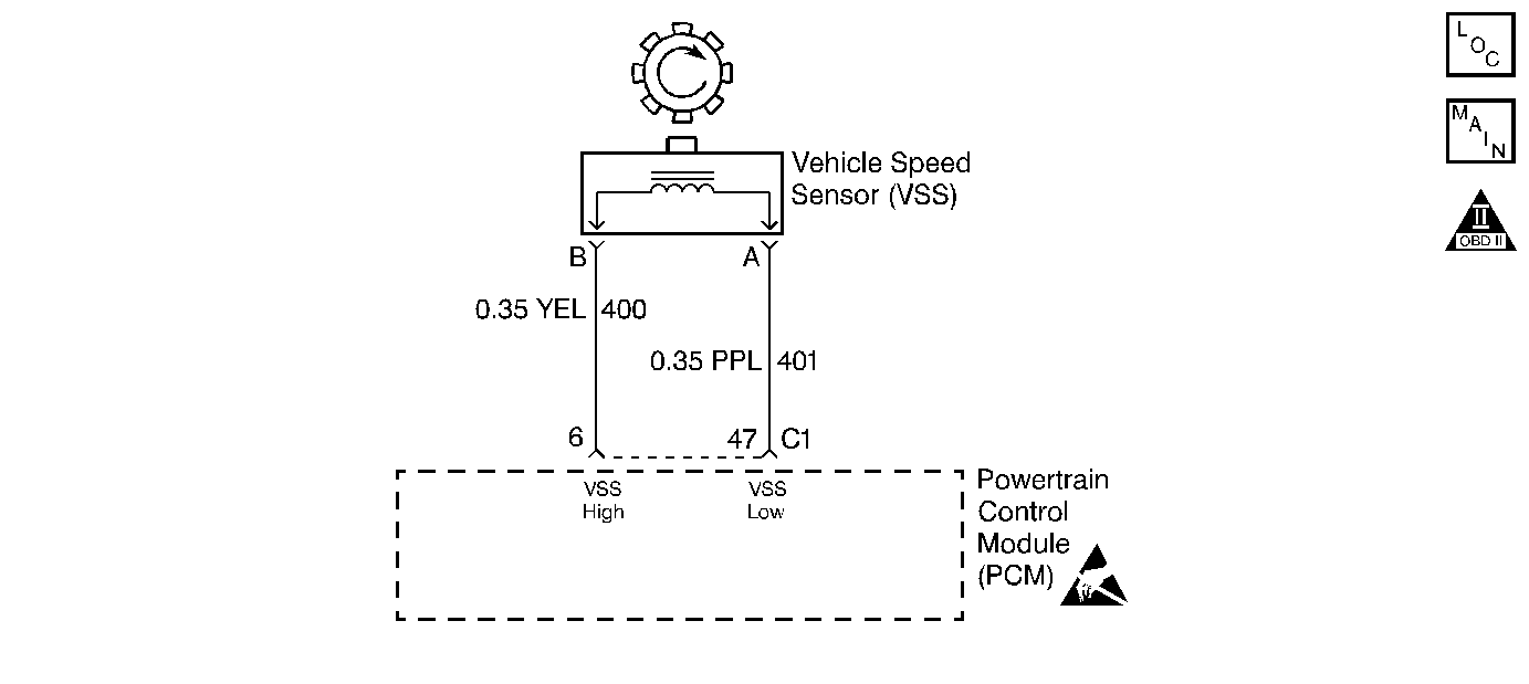
The VSS provides vehicle speed information to the PCM. The VSS is a Permanent Magnet (PM) generator. The VSS produces a pulsing AC voltage. The AC voltage level and the number of pulses increase as the speed of the vehicle increases. The PCM converts the voltage pulses to vehicle speed. A scan tool can display the calculated vehicle speed.
If the PCM detects a low vehicle speed when there is a high engine speed in a drive gear range, then DTC P0502 sets. DTC P0502 is a type B DTC.
Conditions for Setting the DTC
| • | No MAP DTCs P0107 or P0108 |
| • | No TP DTCs P0122 or P0123 |
| • | No TFP Valve Position Switch DTC P1810 |
| • | Not in Park or Neutral |
| • | The TP angle is greater than 12%. |
| • | The engine vacuum is 0-105 kPa. |
| • | The engine speed is greater than 3000 RPM. |
| • | The engine torque is 40-400 lb ft. |
| • | The transmission output speed is less than 150 RPM. |
| • | All conditions met for 2.5 seconds in two consecutive ignition cycles. |
Action Taken When the DTC Sets
| • | The PCM commands second gear only. |
| • | The PCM commands maximum line pressure. |
| • | The PCM freezes shift adapts from being updated. |
| • | The PCM inhibits TCC Solenoid Valve engagement. |
| • | The PCM illuminates the Malfunction Indicator Lamp (MIL). |
Conditions for Clearing the MIL/DTC
| • | The PCM turns OFF the MIL after three consecutive ignition cycles without a failure reported. |
| • | A scan tool can clear the DTC from the PCM history. The PCM clears the DTC from the PCM history if the vehicle completes 40 warm-up cycles without a failure reported. |
| • | The PCM cancels the DTC default actions when the fault no longer exists and the ignition is OFF long enough in order to power down the PCM. |
Diagnostic Aids
| • | A VSS DTC P0502 will set when no vehicle speed is detected at start OFF. |
| • | Inspect the wiring for poor electrical connections at the PCM. Look for the following problems: |
| - | A bent terminal |
| - | A backed out terminal |
| - | A damaged terminal |
| - | Poor terminal tension |
| - | A chafed wire |
| - | A broken wire inside the insulation |
| • | When diagnosing for an intermittent short or open, massage the wiring harness while watching test equipment for changes. |
| • | Test circuits 400 and 401 for Electromagnetic Interferences (EMI) induced by a wiring harness incorrectly routed too near the spark plug wires. |
| • | Incorrect VSS calibration may set DTC P0502. Refer to Service bulletins to ensure that the calibration is current. |
| • | Inspect for a damaged VSS or transmission rotor teeth. |
| • | Ensure that the VSS is correctly aligned and torqued securely to the transmission case. |
Test Description
The numbers below refer to the step numbers on the diagnostic table.
-
This step verifies the integrity of the VSS.
-
This step verifies the integrity of the VSS circuit.
-
This step tests the resistance of the VSS.
Step | Action | Value(s) | Yes | No | ||||||||||||
|---|---|---|---|---|---|---|---|---|---|---|---|---|---|---|---|---|
1 | Was the Powertrain On-Board Diagnostic (OBD) System Check performed? | -- | Go to Powertrain On Board Diagnostic (OBD) System Check , Section 6. | |||||||||||||
2 |
Important:: Before clearing DTCs, use the scan tool in order to record Freeze Frame and Failure Records for reference. The Clear Info function will erase the data. With the drive wheels rotating, does the Trans Output Speed increase with the drive wheel speed? | -- | Go to Diagnostic Aids | |||||||||||||
Is the voltage measurement greater than the specified value? | 0.5V | |||||||||||||||
Measure the resistance between the harness connector terminals C1-6 and C1-47. Is the measured resistance greater than the specified value? | 2820ohms | |||||||||||||||
5 |
Refer to Electrical Diagnosis, Section 8. Did you find and correct a problem? | -- | ||||||||||||||
6 | Is the resistance measured between the harness connector terminals C1-6 and C1-47 less than the specified value? | 1470ohms | ||||||||||||||
7 |
Refer to Electrical Diagnosis, Section 8. Did you find and correct a problem? | -- | ||||||||||||||
Is the measured resistance within the specified range? | 1470-2820ohms | |||||||||||||||
9 |
Did you find a problem? | -- | ||||||||||||||
10 | Replace the VSS. Refer to Vehicle Speed Sensor, in On-Vehicle Service. Is the replacement complete? | -- | -- | |||||||||||||
11 | Inspect the PCM connector for the following problems:
Did you find and correct a problem? | -- | ||||||||||||||
12 | Replace the PCM. Refer to Powertrain Control Module Replacement/Programming , Section 6. Is the replacement complete? | -- | -- | |||||||||||||
13 |
Has the test run and passed? | -- | System OK |
DTC P0502 Vehicle Speed Sensor (VSS) Circuit Low Input 5.7L, VIN P

Circuit Description
The VSS provides vehicle speed information to the PCM. The VSS is a Permanent Magnet (PM) generator. The VSS produces a pulsing AC voltage. The AC voltage level and the number of pulses increase as the speed of the vehicle increases. The PCM converts the voltage pulses to vehicle speed. A scan tool can display the calculated vehicle speed.
If the PCM detects a low vehicle speed when there is a high engine speed in a drive gear range in two consecutive ignition cycles, then DTC P0502 sets. DTC P0502 is a type B DTC.
Conditions for Setting the DTC
| • | No MAP DTCs P0107 or P0108 |
| • | No TP DTCs P0122 or P0123 |
| • | No TFP Valve Position Switch DTC P1810 |
| • | Not in Park or Neutral |
| • | The TP angle is greater than 17%. |
| • | The engine vacuum is 50-80 kPa (7.25-11.60 psi). |
| • | The engine speed is 3000-5500 RPM. |
| • | The transmission output speed is less than 250 RPM. |
| • | All conditions met for 3 seconds in two consecutive ignition cycles. |
Action Taken When the DTC Sets
| • | The PCM commands second gear only. |
| • | The PCM commands maximum line pressure. |
| • | The PCM freezes shift adapts from being updated. |
| • | The PCM inhibits TCC Solenoid Valve engagement. |
| • | The PCM illuminates the Malfunction Indicator Lamp (MIL). |
Conditions for Clearing the MIL/DTC
| • | The PCM turns OFF the MIL after three consecutive ignition cycles without a failure reported. |
| • | A scan tool can clear the DTC from the PCM history. The PCM clears the DTC from the PCM history if the vehicle completes 40 warm-up cycles without a failure reported. |
| • | The PCM cancels the DTC default actions when the fault no longer exists and the ignition is OFF long enough in order to power down the PCM. |
Diagnostic Aids
| • | A VSS DTC P0502 will set when no vehicle speed is detected at start OFF. |
| • | Inspect the wiring for poor electrical connections at the PCM. Look for the following problems: |
| - | A bent terminal |
| - | A backed out terminal |
| - | A damaged terminal |
| - | Poor terminal tension |
| - | A chafed wire |
| - | A broken wire inside the insulation |
| • | When diagnosing for an intermittent short or open, massage the wiring harness while watching test equipment for changes. |
| • | Test circuits 400 and 401 for Electromagnetic Interferences (EMI) induced by a wiring harness incorrectly routed too near the spark plug wires. |
| • | Incorrect VSS calibration may set DTC P502. Refer to service bulletins to ensure that the calibration is current. |
| • | Inspect for a damaged VSS or transmission rotor teeth. |
| • | Ensure that the VSS is correctly aligned and torqued securely to the transmission case. |
Test Description
The numbers below refer to the step numbers on the diagnostic table.
-
Disable the traction system when performing this step. When the ignition key is cycled to the OFF position and then cycled back ON, the traction control system defaults to ON.
-
This step verifies the integrity of the VSS.
-
This step verifies the integrity of the VSS circuit.
-
This step tests the resistance of the VSS.
Step | Action | Value(s) | Yes | No | ||||||||||||
|---|---|---|---|---|---|---|---|---|---|---|---|---|---|---|---|---|
1 | Was the Powertrain On-Board Diagnostic (OBD) System Check performed? | -- | Go to Powertrain On Board Diagnostic (OBD) System Check , Section 6. | |||||||||||||
Important:: Before clearing DTCs, use the scan tool in order to record Freeze Frame and Failure Records for reference. The Clear Info function will erase the data. With the drive wheels rotating, does the Trans Output Speed increase with the drive wheel speed? | -- | Go to Diagnostic Aids | ||||||||||||||
Is the voltage measurement greater than the specified value? | 0.5V | |||||||||||||||
Using the J 39200 DMM, measure the resistance between harness connector terminals C1-31 and C1-32. Is the measured resistance greater than the specified value? | 2820ohms | |||||||||||||||
5 |
Refer to Troubleshooting Procedures, Section 8. Did you find and correct a problem? | -- | ||||||||||||||
6 | Is the resistance measured between harness connector terminals C1-31 and C1-32 less than the specified value? | 1470ohms | ||||||||||||||
7 |
Refer to Troubleshooting Procedures, Section 8. Did you find and correct a problem? | -- | ||||||||||||||
Is the measured resistance within the specified range? | 1470-2820ohms | |||||||||||||||
9 |
Did you find and correct a problem? | -- | ||||||||||||||
10 | Replace the VSS. Refer to Speed Sensor Replacement, in On-Vehicle Service. Is the replacement complete? | -- | -- | |||||||||||||
11 | Inspect the PCM connector for the following problems:
Did you find and correct a problem? | -- | ||||||||||||||
12 | Replace the PCM. Refer to Powertrain Control Module Replacement/Programming , Section 6. Is the replacement complete? | -- | -- | |||||||||||||
13 |
Has the test run and passed? | -- | System OK |
