For 1990-2009 cars only
Removal Procedure
- Remove the left instrument panel (I/P) sound insulator. Refer to Instrument Panel Insulator Panel Replacement - Left Side .
- Remove the knee bolster trim panel. Refer to Driver Knee Bolster Panel Replacement .
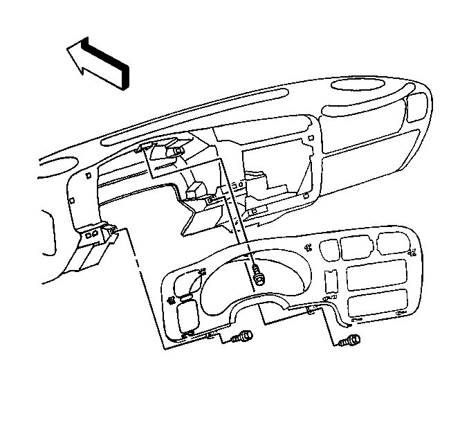
- Remove the screws that retain the accessory trim plate to the I/P.
- Remove the I/P accessory trim plate by releasing the retaining clips.
- Position the I/P accessory trim plate in order to remove the control switches.

| • | Remove the selectable 4WD switch, if equipped. Refer to Transfer Case Shift Control Switch Replacement in Transfer Case - NVG 233-NP1 or Transfer Case Shift Control Switch Replacement in Transfer Case - NVG 236-NP8. |
| • | Remove the headlamp switch. Refer to Headlamp Switch Replacement in Lighting Systems. |
Installation Procedure
- Position the I/P accessory trim plate in order to install the control switches.
- Install the instrument panel accessory trim plate clips to the instrument panel.
- Install the screws that retain the accessory trim plate to the I/P.
- Install the knee bolster trim panel. Refer to Driver Knee Bolster Panel Replacement .
- Install the left I/P sound insulator. Refer to Instrument Panel Insulator Panel Replacement - Left Side .

| • | Install the selectable 4WD switch, if equipped. Refer to Transfer Case Shift Control Switch Replacement in Transfer Case - NVG 233-NP1 or Transfer Case Shift Control Switch Replacement in Transfer Case - NVG 236-NP8. |
| • | Install the headlamp switch. Refer to Headlamp Switch Replacement in Lighting Systems. |
Notice: Refer to Fastener Notice in the Preface section.
Tighten
Tighten the screws to 1.9 N·m (17 lb in).
