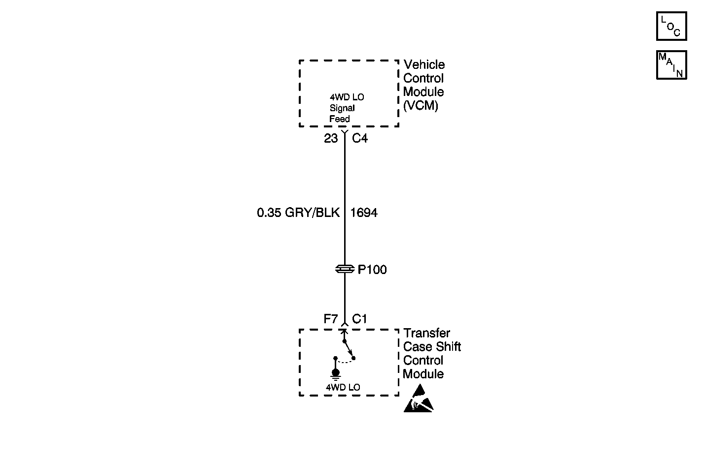
Circuit Description
The 4WD LO circuit is used to inform the PCM/VCM when the transfer case has been placed into 4WD LO mode. The PCM/VCM supplies the circuit with a 12 V signal. When the transfer case is placed into 4WD LO, the transfer case shift control module pulls the 12 V signal low which is then sensed by the PCM/VCM.
This DTC detects an internal module fault or a short to voltage on the 4WD LO signal feed circuit.
Conditions for Setting the DTC
| • | After the system turns the output on, (grounding the 4WD LO Signal Feed Circuit), and reads back a high voltage, the DTC is set. The system will not attempt it again during that ignition cycle. |
| • | The transfer case shift control module reads back a high voltage when a low voltage is expected on the 4WD LO Signal Feed Circuit. |
Action Taken When the DTC Sets
| • | May affect the transmission shift points. |
| • | The SERVICE indicator (AWD/4WD) lamp will be latched on for the remainder of the current ignition cycle. |
Conditions for Clearing the DTC
| • | The transfer case shift control module will clear the DTC if the condition for setting the DTC no longer exits. |
| • | A history DTC will clear after 100 consecutive ignition cycles without a fault present. |
| • | History DTCs can be cleared using a scan tool. |
Test Description
The numbers below refer to the step numbers on the diagnostic table.
-
Tests the 4WD LO circuit for voltage.
-
Tests the 4WD LO circuit for a short to voltage.
-
Tests the 4WD LO circuit for an open or high resistance.
-
Repairs the 4WD LO circuit for a short to voltage.
Step | Action | Value(s) | Yes | No |
|---|---|---|---|---|
1 | Was the Transfer Case Diagnostic System Check performed? | -- | Go to Step 2 | Go to Diagnostic System Check |
Does the DMM indicate battery voltage? | -- | Go to Step 3 | Go to Step 4 | |
Does the DMM continue to show battery voltage? | -- | Go to Step 5 | Go to Step 7 | |
Test the 4WD LO circuit for an open or high resistance. Refer to Circuit Testing and Wiring Repairs in Wiring Systems. Was the condition found and corrected? | -- | Go to Step 8 | Go to Step 6 | |
5 | Repair the 4WD LO circuit for a short to voltage. Refer to Wiring Repairs in Wiring Systems. Is the repair complete? | -- | Go to Step 8 | -- |
6 | Replace the powertrain control module. Refer to Powertrain Control Module Replacement/Programming for the 2.2L engine, Powertrain Control Module Replacement/Programming for the 2.2L (L43) engine, or VCM Replacement/Programming for the 4.3L engine. Is the replacement complete? | -- | Go to Step 8 | -- |
7 | Replace the transfer shift case control module. Refer to Transfer Case Shift Control Module Replacement . Is the replacement complete? | -- | Go to Step 8 | -- |
8 |
Does the DTC reset? | -- | Go to Step 2 | System OK |
