Circuit Description
The Fuel Level sensor is an important input to the VCM for the Enhanced Evaporative System Diagnostic. The VCM needs the fuel level information in order to know the volume of fuel in the tank. The fuel level affects the rate of change in the air pressure in the EVAP system. Several of the Enhanced Evaporative System Diagnostic sub-test are dependent upon the correct fuel level information. The diagnostic will not run when the tank is greater than 85% or less than 15% full. (This sensor signal disables the misfire when the fuel levels are less than 15%). This DTC is a type D DTC.
Conditions for Setting the DTC
| • | The Fuel Tank Level Slosh Test is completed. |
| • | The Tank Level Main Test is completed. |
| • | The Fuel Tank Level Data is Valid. |
| • | The Fuel Level signal is unchanged over a distance of 200 miles. |
Action Taken When the DTC Sets
| • | The control module stores the DTC in history after the first failure but will not illuminate the malfunction indicator lamp (MIL). |
| • | The control module records the operating conditions at the time the diagnostic fails. The control module stores the failure information in the scan tools Freeze Frame/Failure Records. |
Conditions for Clearing the MIL/DTC
The VCM turns OFF the MIL after 3 consecutive driving trips without a fault condition present. A history DTC will clear if no fault conditions have been detected for 40 warm-up cycles (the coolant temperature has risen 22°C (40°F) from the start-up coolant temperature and the engine coolant temperature exceeds 71°C (160°F) during that same ignition cycle) or the scan tool clearing feature has been used.
Test Description
The number below refers to the step number in the diagnostic table.
Step | Action | Value(s) | Yes | No |
|---|---|---|---|---|
1 | Was the On-Board Diagnostic (OBD) System Check performed? | -- | ||
2 |
Are the levels approximately the same? | -- | ||
3 |
Did the vehicle fuel gauge reading change? | -- | ||
Does the scan tool and the fuel gauge indicate the specified values? | 0% Empty | |||
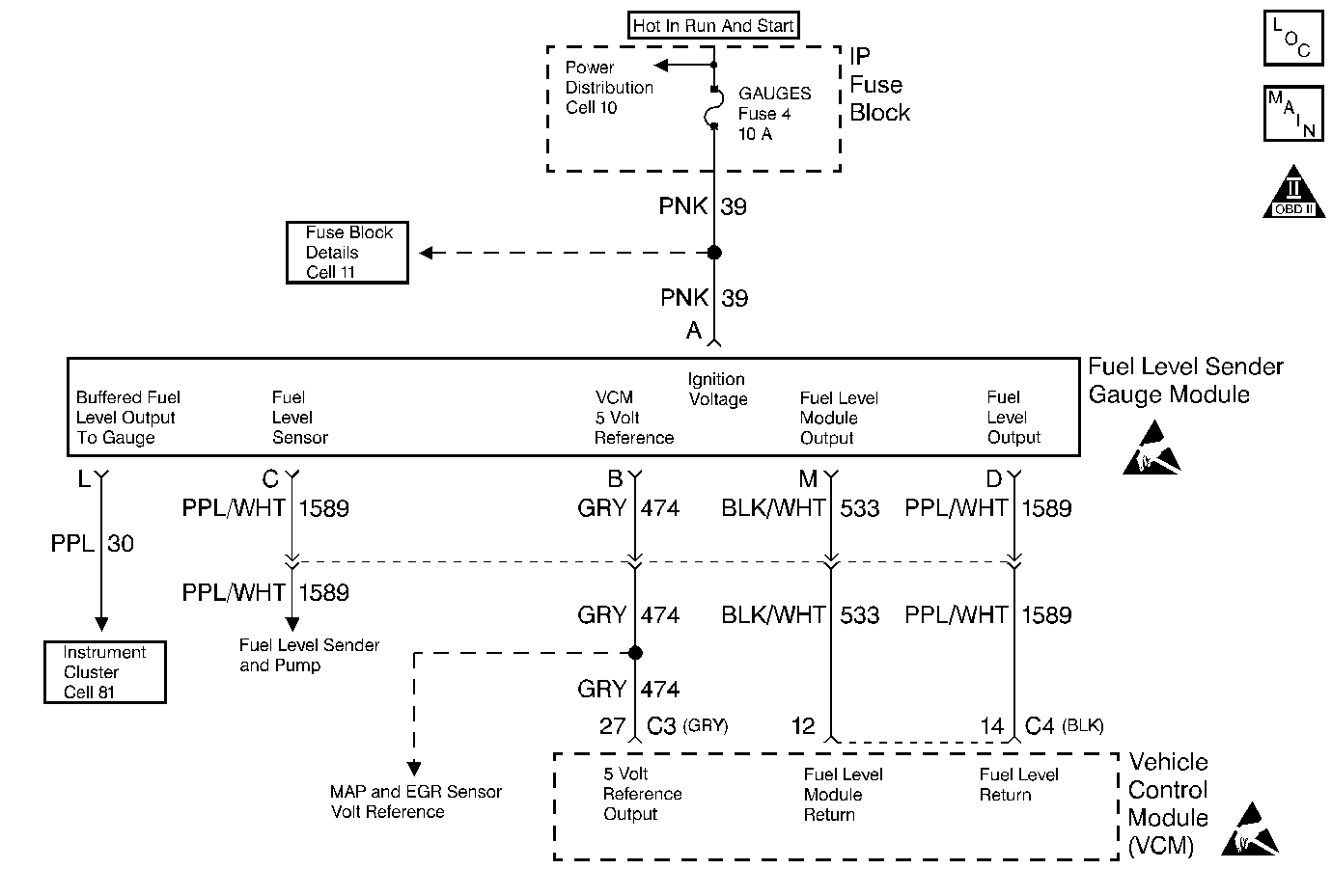
5 | Refer to Engine Electrical for Fuel Sender Gauge Module Diagnosis. | -- | -- | -- |
6 | Replace VCM. Important: If the VCM is malfunctioning, program the new VCM. Refer to VCM Replacement/Programming . Is the action complete? | -- | -- | |
7 |
Does the scan tool indicate that this diagnostic Ran and Passed? | -- | ||
8 | Using the scan tool, select the Capture Info and the Review Info. Are any DTCs displayed that have not been diagnosed? | -- | Go to the Applicable DTC Table | System OK |
