For 1990-2009 cars only
Tools Required
| • | J 45059 Angle Meter |
| • | KM-470-B Angular Torque Gage |
Piston Inspection
- Inspect the connecting rod for bending or twisting. If the connecting rod is bent or twisted, replace the connecting rod.
- Inspect the connecting rod bearings.
- Inspect the connecting rod lower end for wear.
- Inspect the connecting rod upper end for scoring.
- Inspect the crankshaft rod bearing journal for wear. Refer to Engine Mechanical Specifications .
- Inspect the piston for scoring, cracks, and wear.
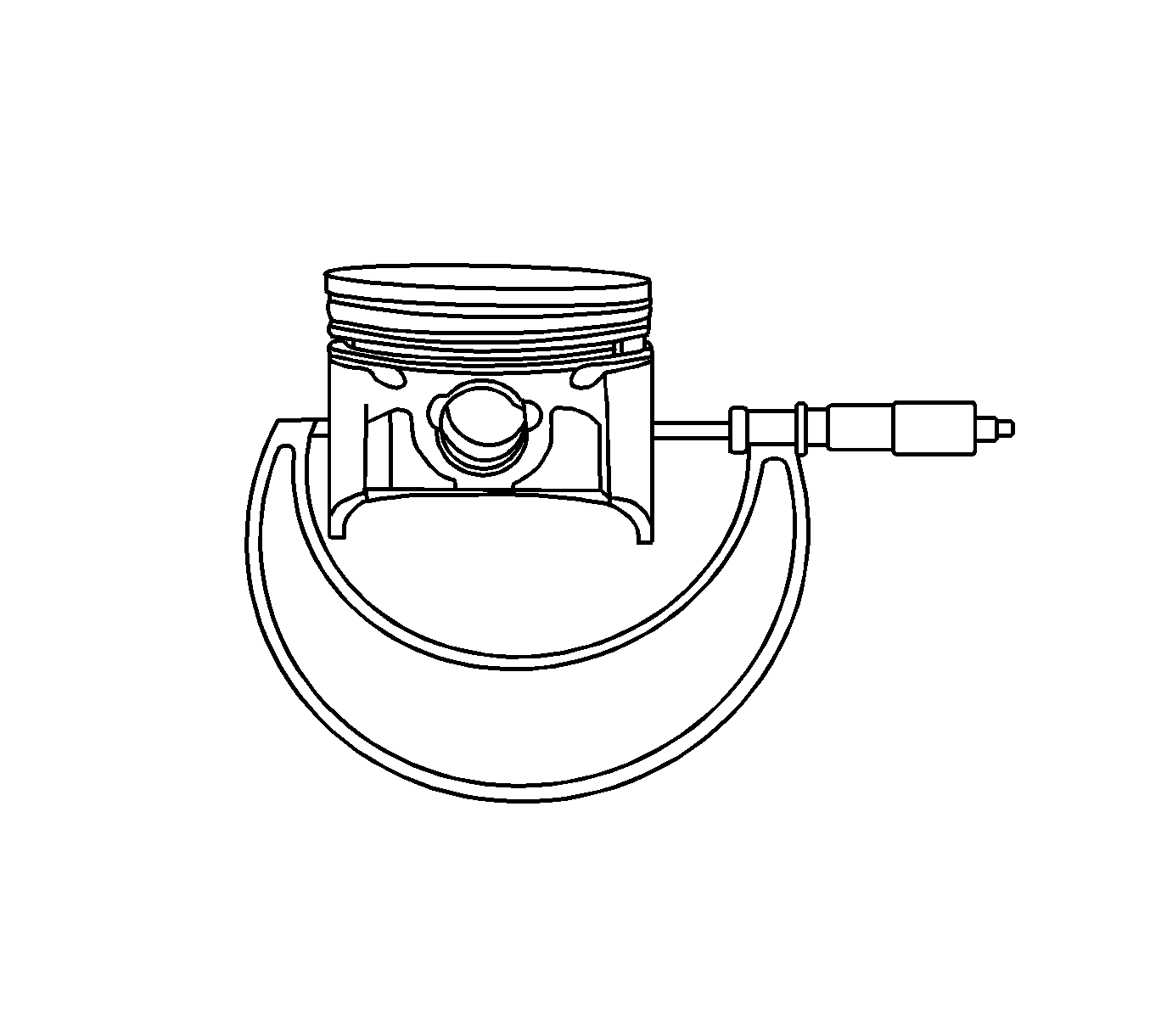
- Inspect the piston for taper using a micrometer.
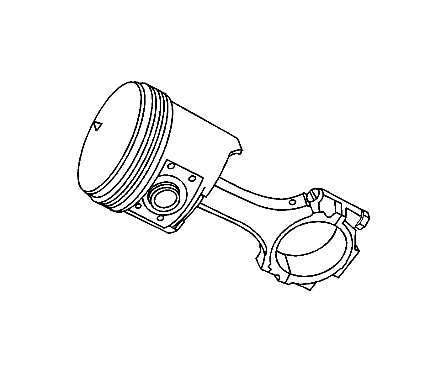
- Inspect the piston for fit to the connecting rod.
- Inspect the engine block deck surface for flatness using a straight edge and a feeler gage. Refer to Engine Mechanical Specifications .
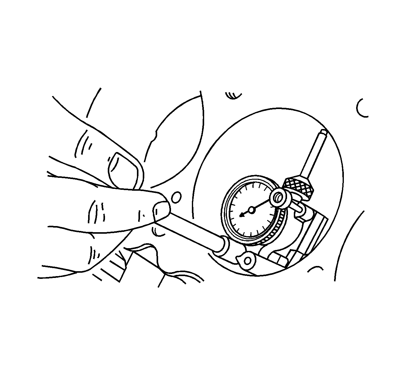
- Inspect the bearing bore for concentricity and alignment using a bore gage. Refer to Engine Mechanical Specifications . If the bearing bore is beyond specifications, replace the engine block.
- Inspect the engine block cylinder bore for wear, runout, ridging and taper using a bore gage. Refer to Engine Mechanical Specifications .
- Inspect the engine block cylinder bore for glazing.
Connecting Rod Bearing Inspection
- Coat the connecting rod bearings with engine oil.
- Install the upper connecting rod bearings into the connecting rod journals.
- Install the lower connecting rod bearings into the connecting rod bearing caps.
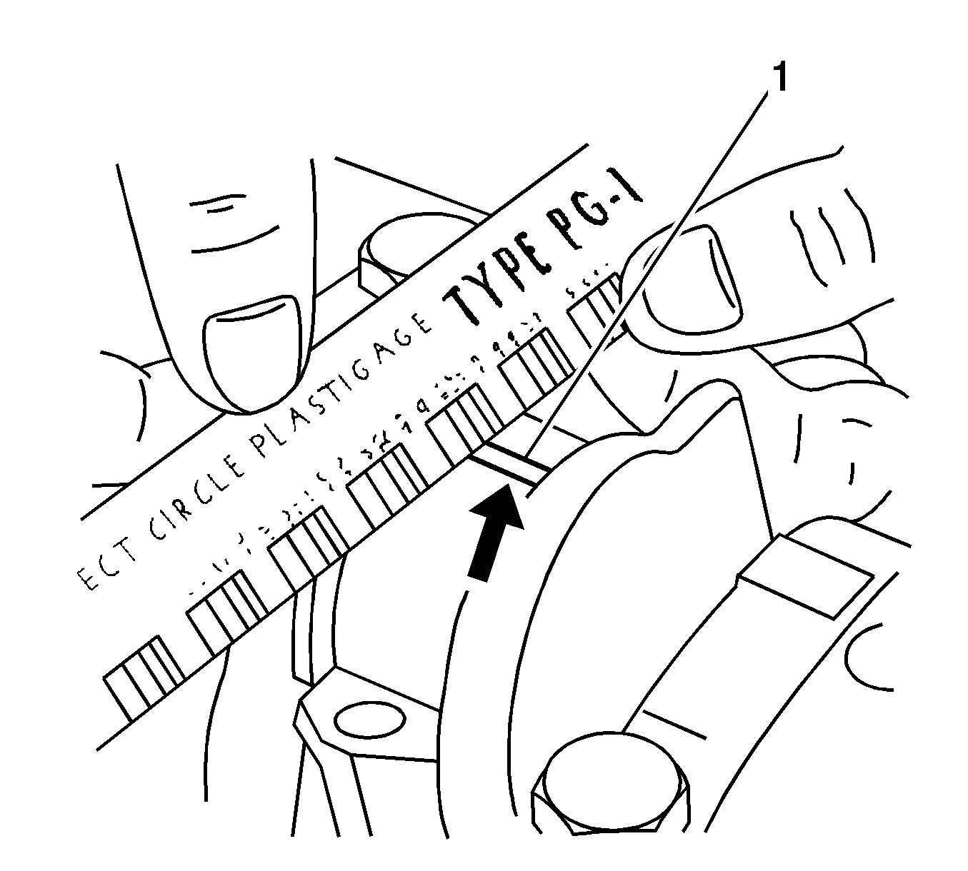
- Measure all of the connecting rod bearing clearances using a commercially available plastic gaging (1), ductile plastic threads.
- Cut the plastic gaging threads to the length of the bearing width. Lay them axially between the connecting rod journals and the connecting rod bearings.
- Install the connecting rod bearing caps.
- Install the connecting rod bearing cap bolts.
- Using the J 45059 or the KM-470-B (1), tighten the crankshaft cap bolts another 30 degrees plus 15 degrees.
- Remove the connecting rod bearing caps.
- Measure the width of the flattened plastic thread of the plastic gaging (1) using the scale printed on the plastic gaging package. Plastic gaging is available for different tolerance ranges.
- Inspect the bearing clearance for permissible tolerance ranges. Refer to Engine Mechanical Specifications .
Caution: Refer to Battery Disconnect Caution in the Preface section.
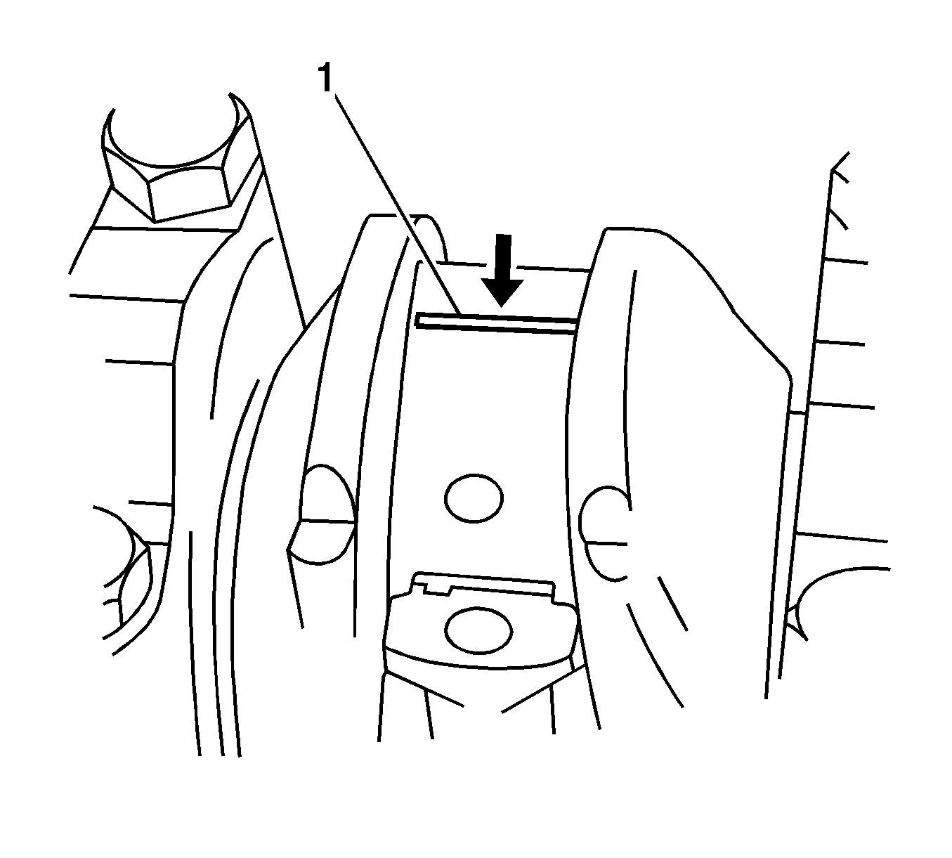
Important: Grease the connecting rod journals and lubricate the connecting rod bearings slightly so that the plastic gaging thread does not tear when the connecting rod bearing caps are removed.
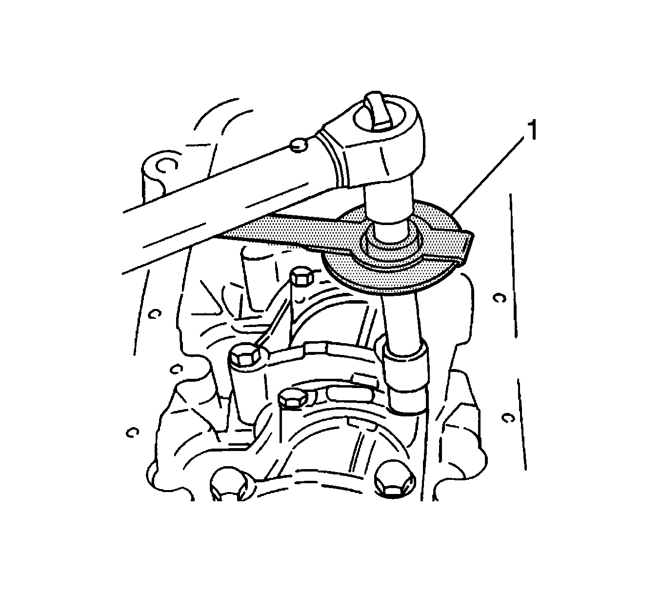
Notice: Refer to Fastener Notice in the Preface section.
Tighten
Tighten the connecting rod bearing cap bolts to 25 N·m (18 lb ft).
