For 1990-2009 cars only
Tools Required
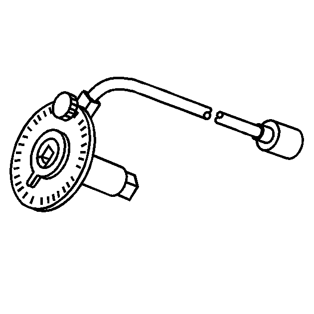
| • | J 42492-A Timing Belt Adjuster |
| • | KM-470-B Angular Torque Gage |
| • | J 45059 Angle Meter |
Adjustment Procedure
- Disconnect the negative battery cable.
- Disconnect the intake air temperature (IAT) sensor connector.
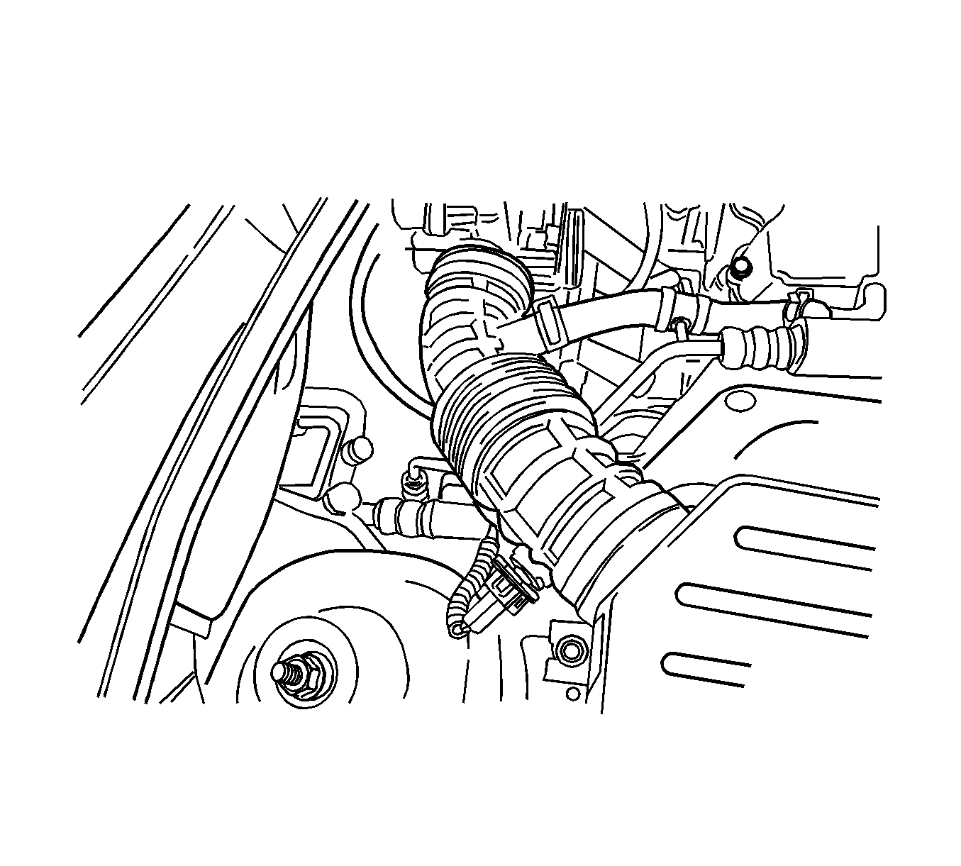
- Disconnect the air intake tube from the throttle body.
- Disconnect the breather tube from the valve cover.
- Remove the air cleaner housing bolts.
- Remove the air cleaner housing.
- Remove the right front wheel. Refer to Tire and Wheel Removal and Installation .
- Remove the right front wheel well splash shield.
- Remove the serpentine accessory drive belt. Refer to Power Steering Pump Hoses and Pipes Replacement .
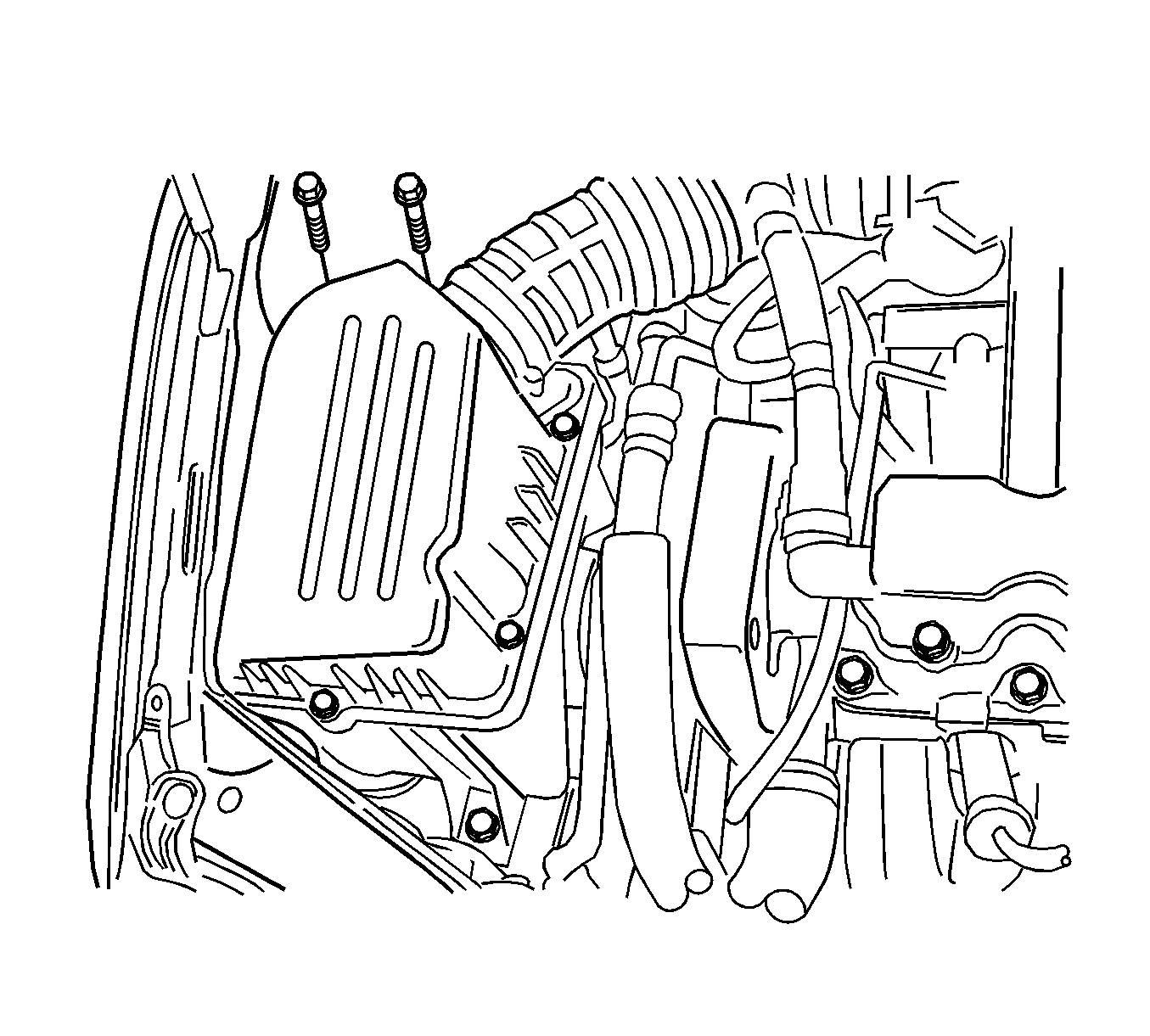
- Remove the upper timing belt cover bolts.
- Remove the upper timing belt cover.
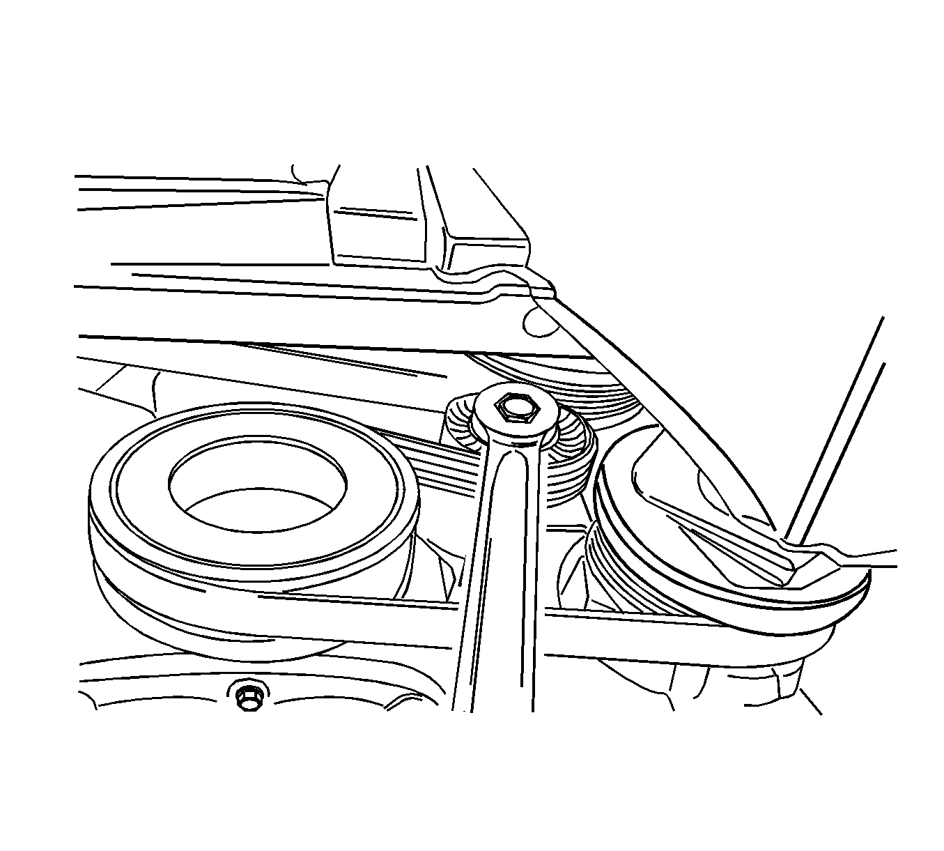
- Remove the crankshaft pulley bolt.
- Remove the crankshaft pulley.
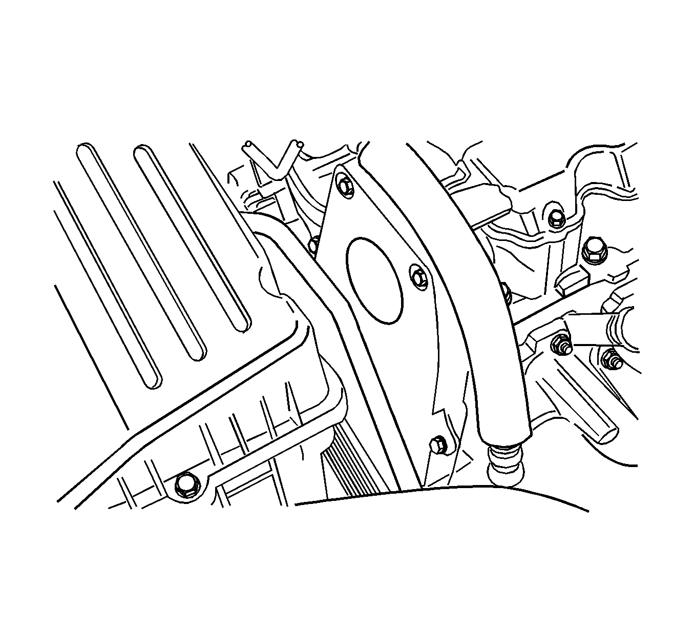
- Remove the lower timing belt cover bolts.
- Remove the lower timing belt cover.
- Install the crankshaft pulley bolt.
- Rotate the crankshaft at least 1 full turn clockwise using the crankshaft pulley bolt.
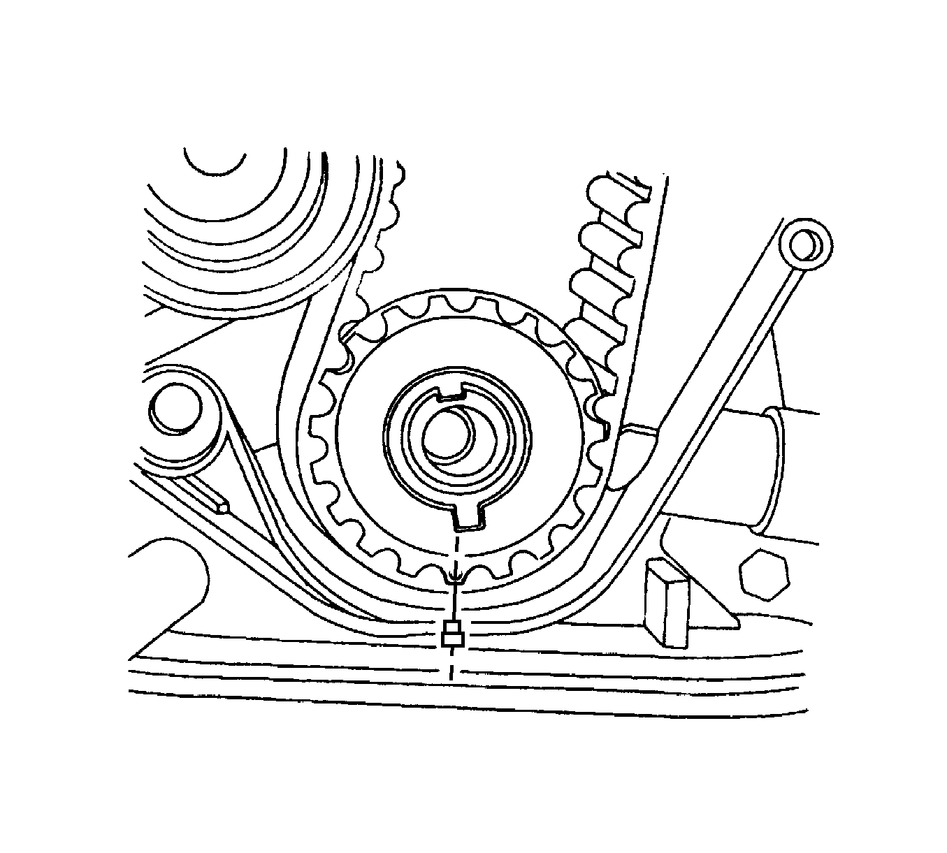
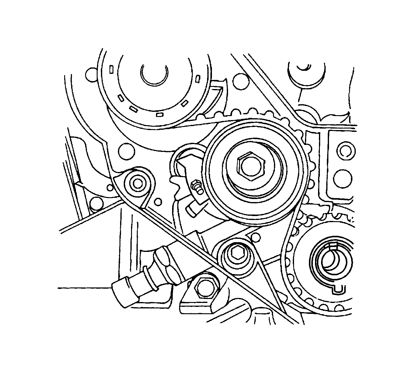
- Align the dot on the crankshaft gear to the notch at the bottom of the rear timing belt cover.
- Align the camshaft gear timing mark to the notch at the top of the rear timing belt cover.
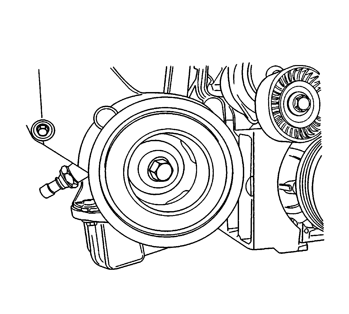
- Slightly loosen the 3 coolant pump retaining bolts.
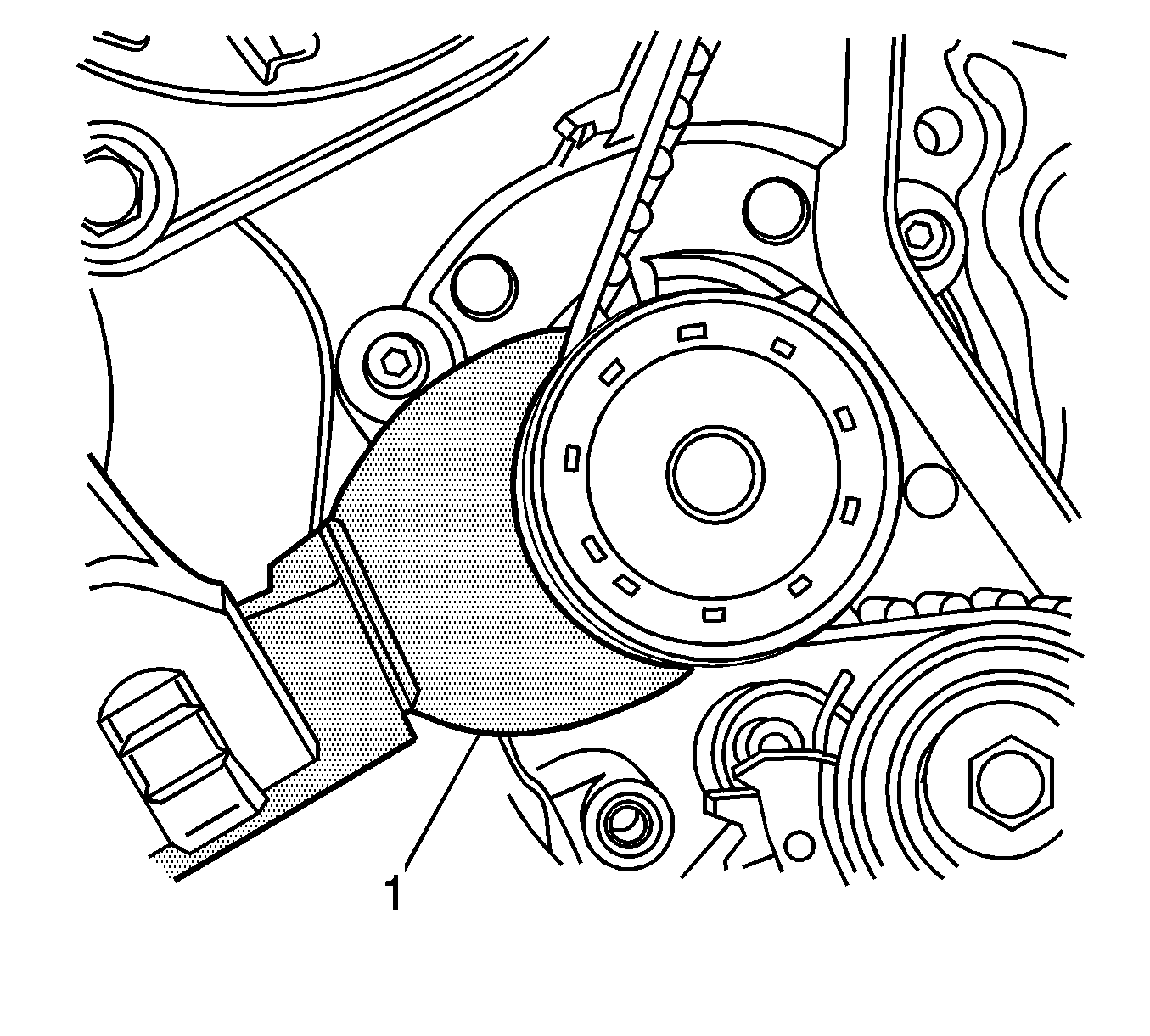
- Using the J 42492-A (1), rotate the coolant pump clockwise to add the highest tension to the timing belt.
- Tighten the coolant pump retaining bolts loosely.
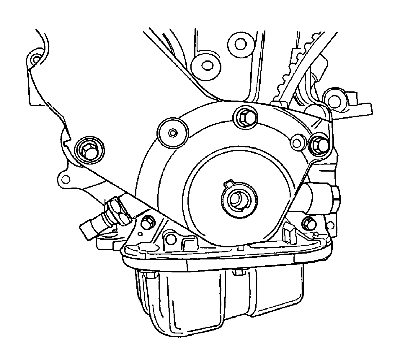
- Align the adjust arm hole of the timing belt automatic tensioner to the hole in the timing belt automatic tensioner bracket.
- Insert a 4.5 mm driver through the adjust arm hole and the tensioner bracket hole.
- Rotate the crankshaft 2 full turns clockwise using the crankshaft pulley bolt.
- Rotate the crankshaft at least 1 full turn clockwise using the crankshaft pulley bolt.
- Remove the driver from the timing belt automatic tensioner.
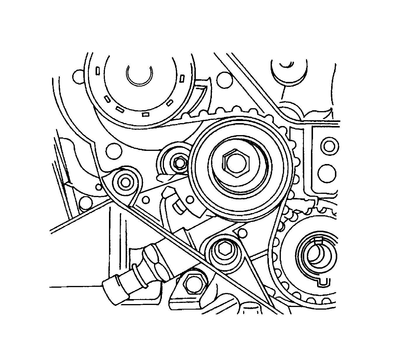
- Loosen the coolant pump retaining bolts.
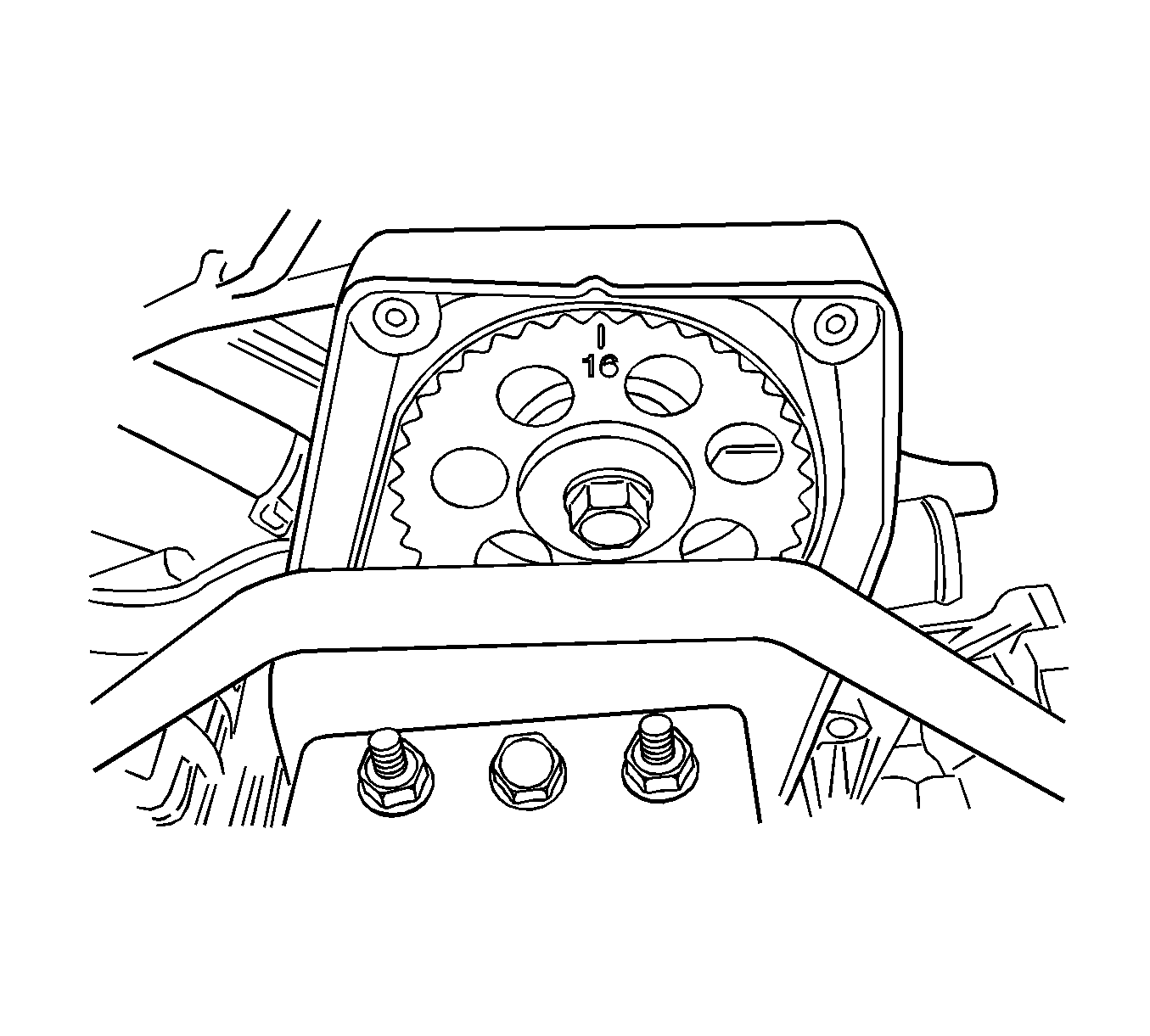
- Rotate the coolant pump until the adjust arm pointer of the timing belt automatic tensioner is aligned with the notch in the timing belt automatic tensioner bracket.
- Tighten the coolant pump retaining bolts.
- Remove the crankshaft pulley bolt.
- Install the lower timing belt cover.
- Install the lower timing belt cover bolts.
- Install the crankshaft pulley.
- Install the crankshaft pulley bolt.
- Install the upper timing belt cover.
- Install the upper timing belt cover bolts.
- Install the serpentine accessory drive belt. Refer to Power Steering Pump Hoses and Pipes Replacement .
- Install the right front wheel well splash shield.
- Install the right front wheel. Refer to Tire and Wheel Removal and Installation .
- Install the air cleaner housing.
- Install the air cleaner housing bolts.
- Connect the air intake tube to the throttle body.
- Connect the breather tube to the valve cover.
- Connect the IAT sensor connector.
- Connect the negative battery cable.
Caution: Refer to Battery Disconnect Caution in the Preface section.
Notice: Refer to Belt Dressing Notice in the Preface section.
Notice: Refer to Fastener Notice in the Preface section.
Tighten
Tighten the coolant pump retaining bolts to 10 N·m (89 lb in).
Tighten
Tighten the lower timing belt cover bolts to 10 N·m (89 lb in).
Tighten
| • | Tighten the crankshaft pulley bolt to 95 N·m (70 lb ft) using a torque wrench. |
| • | Using the J 45059 or the KM-470-B , tighten the crankshaft pulley bolt another 30 degrees plus 15 degrees. |
Tighten
Tighten the upper timing belt cover bolts to 10 N·m (89 lb in).
Notice: Refer to Belt Dressing Notice in the Preface section.
Tighten
Tighten the air filter housing bolts to 12 N·m (106 lb in).
