Drive Pinion Bearings Replacement 10.5 Inch Axle
Special Tools
| • | J 8092 Universal Driver Handle - ¾ in - 10 |
| • | J 8608 Pinion Bearing Cup Installer |
| • | J 8614-01 Flange Holder and Remover |
| • | J 22761 Side Bearing Installer |
| • | J 22912-B Bearing Remover |
| • | J 24433 Pinion Bearing Installer |
| • | J 37624 Pinon Bearing Installer |
| • | J 44414 Pinion Oil Seal Installer |
Removal Procedure
- Raise and support the vehicle. Refer to
Lifting and Jacking the Vehicle.
- Remove the differential assembly. Refer to
Differential Replacement.
- Remove the pinion yoke and the oil seal. Refer to
Drive Pinion Flange/Yoke and/or Oil Seal Replacement.
- Remove the drive pinion housing assembly. Refer to
Drive Pinion Bearings Replacement.
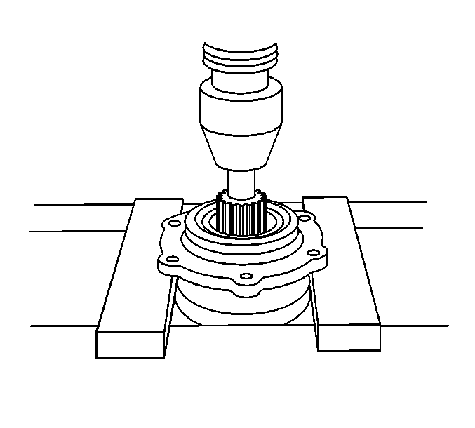
- Using a press and the appropriate tool, remove the drive pinion gear pinion.
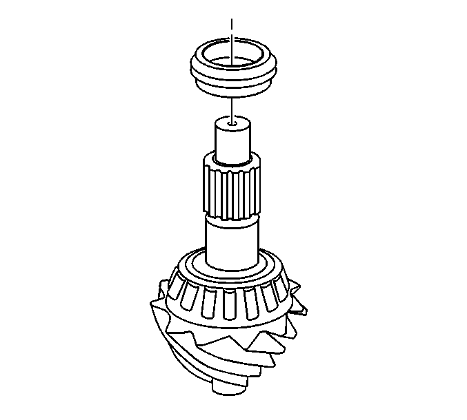
- Remove the collapsible spacer.
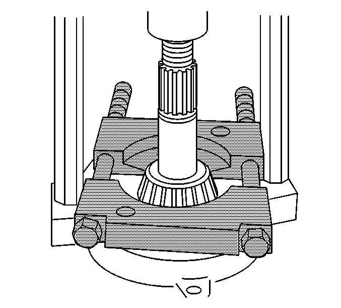
- Using the
J 22912-B remover
and a hydraulic press, remove the inner drive pinion bearing.
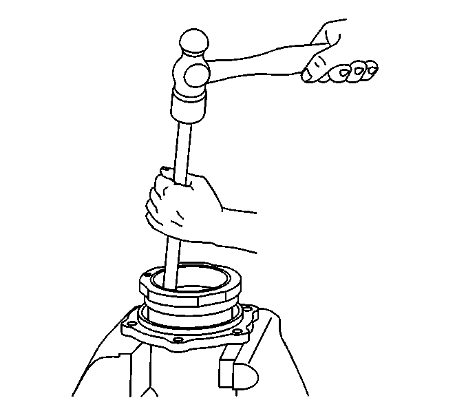
Note: Insert the brass drift in the slots to remove the bearing cup and move the drift back and forth between one side of the cup and the other in order to work the cups out of the retainer evenly.
- Using a brass drift and a hammer, remove the outer pinion bearing cup.
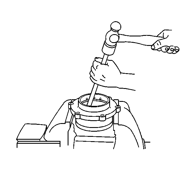
Note: Insert the brass drift in the slots to remove the bearing cup and move the drift back and forth between one side of the cup and the other in order to work the cups out of the retainer evenly.
- Using a brass drift and a hammer, remove the inner pinion bearing cup.
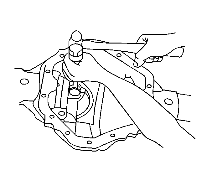
- Using a brass drift and a hammer, remove the pinion gear pilot bearing.
Installation Procedure
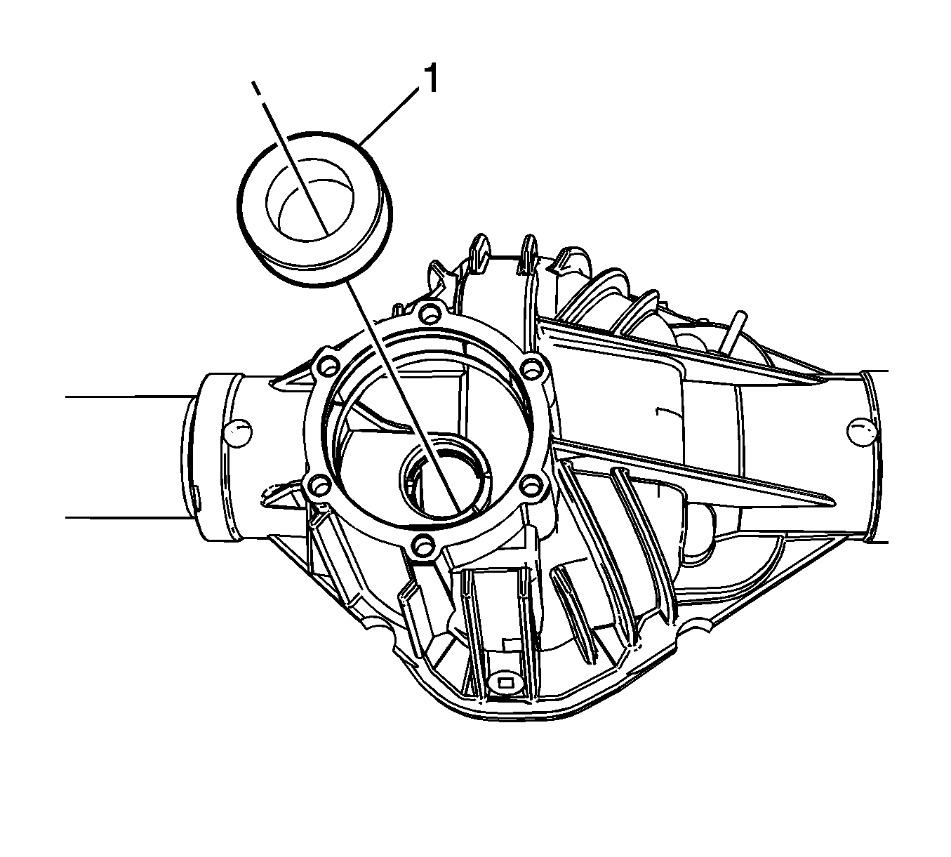
Note: Ensure that the drive pinion gear pilot bearing is as square as possible in the differential housing before installation.
- Position the drive pinion gear pilot bearing (1) in the differential housing (2).
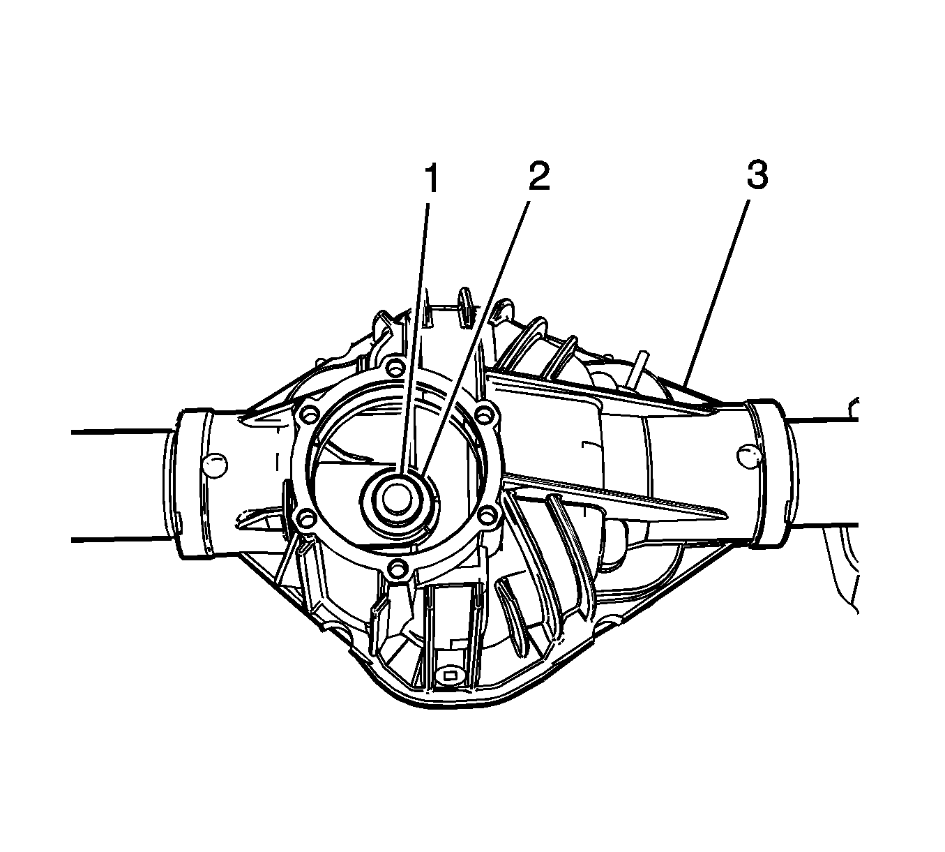
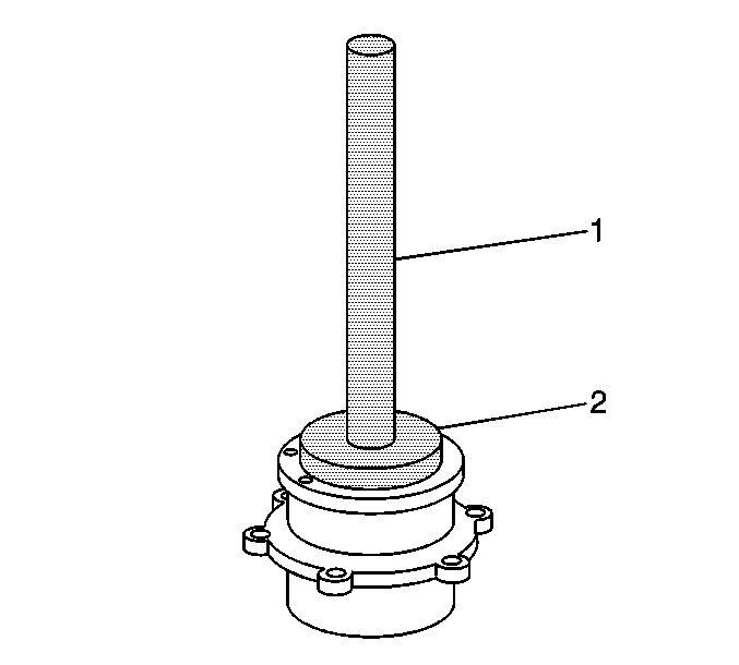
- Using the
J 22761 installer
(1) and the
J 8092 handle
(2),
install the drive pinion gear pilot bearing in the differential housing (3).
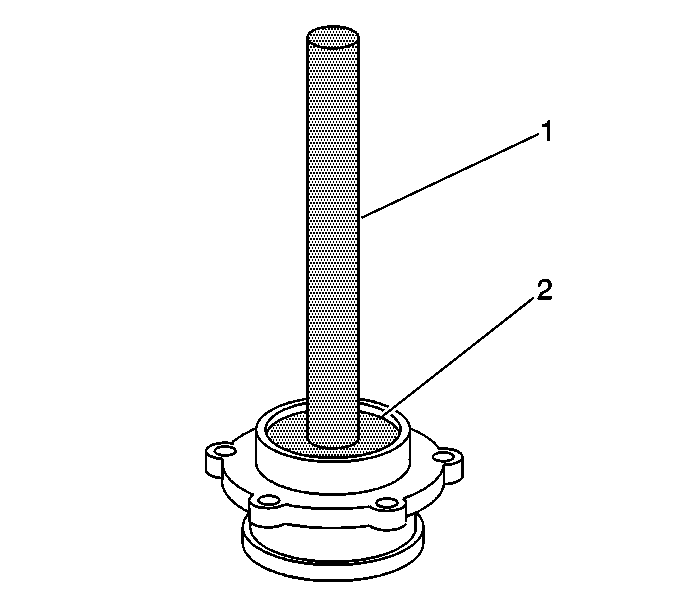
- Using the
J 37624 installer
(2) and the
J 8092 handle
(1), install
the inner pinion bearing cup in the pinion gear bearing retainer.
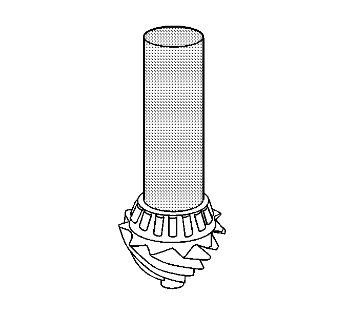
- Using the
J 8608 Pinion Bearing Cup Installer
(2) and the
J 8092 handle
(1),
install the outer pinion bearing cup in the pinion gear bearing retainer.
Note: Press the bearing on until the cone seats on the pinion.
- Using the
J 24433 installer
and a hydraulic press, install the inner pinion bearing.

- Install the new collapsible spacer.
- Lubricate the pinion bearings with axle lubricant. Refer to
Fluid and Lubricant Recommendations.
- Install the outer pinion bearing into the pinion bearing retainer.
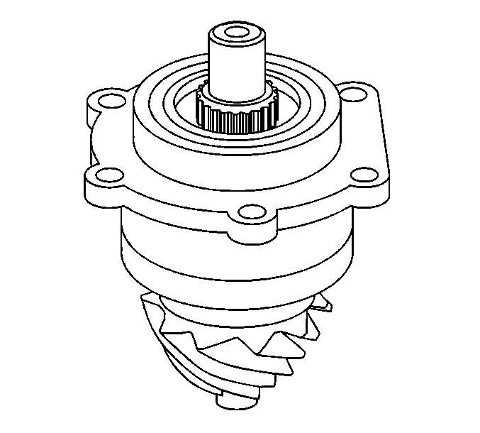
- Using the
J 44414 installer
, install the new pinion oil seal.
- Install the pinion in the pinion gear bearing retainer.
- Install the drive pinion flange/yoke. Refer to
Drive Pinion Flange/Yoke and/or Oil Seal Replacement
Note: Do not apply sealant to the pinion gear bearing retainer at this time.
- Install the original shim to the pinion bearing retainer. If the original shim is not available, install a
0.41 mm (0.016 in) shim to build pinion depth.
- Install the pinion gear bearing retainer to the axle housing. Refer to
Drive Pinion Housing and/or Seal Replacement
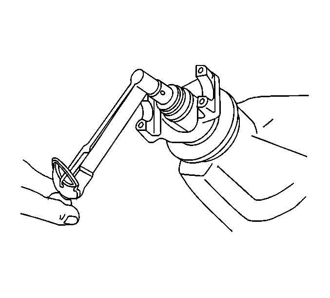
- Using an inch-pound torque wrench, measure the rotating torque of the pinion should be between
1.0-2.3 N·m (10-20 lb in) for used bearings or
1.7-3.4 N·m
(15-30 lb in) for new bearings.
- If the rotating torque measurement is below
1.0 N·m (10 lb in) for used bearings, or
1.7 N·m (15 lb in) for new bearings, use the
J 8614-01 holding tool
and continue to tighten the pinion nut, in small increments, as needed, until the rotating torque is between
1.0-2.3 N·m (10-20 lb in) for used bearings, or
1.7-3.4 N·m (15-30 lb in) for new bearings.
- Once the specified torque is obtained, rotate the pinion several times to ensure the bearings have seated.
Recheck the rotating torque and adjust if necessary.
- Install the differential assembly. Refer to
Differential Replacement.
- Adjust the differential side bearing preload. Refer to
Differential Carrier Bearing Preload Adjustment.
- Adjust the drive pinion gear pinion depth, if needed. Refer to
Pinion Depth Adjustment.
- Adjust the backlash. Refer to
Backlash Adjustment.
- Fill the axle with lubricant. Refer to
Rear Axle Lubricant Replacement.
- Remove the support and lower the vehicle.
Drive Pinion Bearings Replacement 8.6 Inch Axle
Special Tools
| • | DT 47688 Pinion Bearing Remover |
| • | J 8092 Universal Drive Handle 3/4 in--10 |
| • | J 8611-01 Pinion Bearing Cup Installer |
| • | J 22828 Input Shaft Gear Installer |
| • | J 22912-B Bearing Puller |
| • | J 36614 Inner Pinion Bearing Installer |
| • | J 45870 Inner Pinion Bearing Race Installer |
Disassemble Procedure
- Raise and support the vehicle. Refer to
Lifting and Jacking the Vehicle.
- Remove the differential assembly. Refer to
Differential Replacement.
- Remove the differential drive pinion gear. Refer to
Drive Pinion and Ring Gear Replacement.
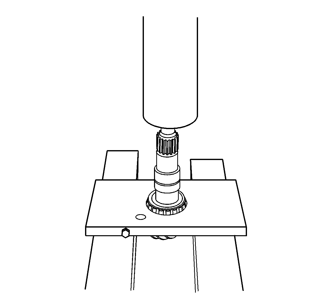
- For the 8.6 inch axle, use the
DT 47688 remover
and a press remove the drive pinion bearing and the spacer.

- For the 9.5LD inch axle, use the
J 22912-B puller
and a press to remove the drive pinion bearing.
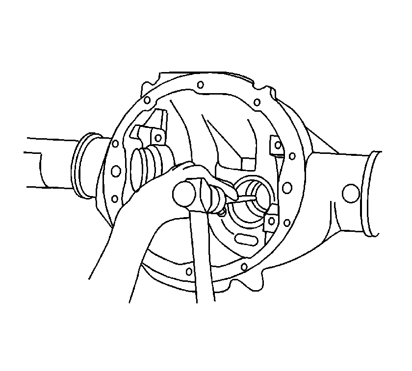
Note: When performing the following service procedure, move the drift back and forth between one side of the cup and the other in order to work the cups out of the housing evenly
- Using a hammer and a brass drift in the slots provided, remove the outer pinion bearing cup from the axle housing.
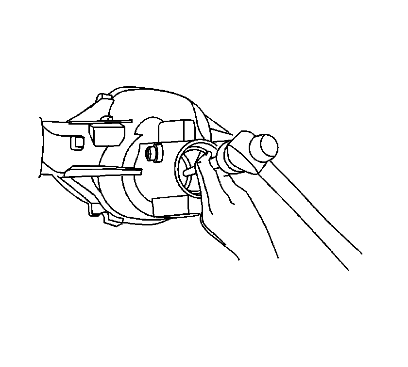
Note: When performing the following service procedure, move the drift back and forth between one side of the cup and the other in order to work the cups out of the housing evenly
- Using a hammer and a brass drift in the slots provided, remove the inner pinion bearing cup from the axle housing.
Assemble Procedure
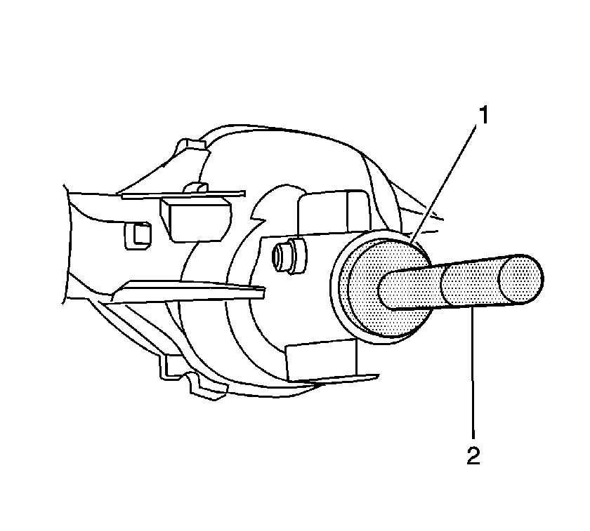
- Using the
J 8092 handle
(2) and the
J 8611-01 installer
(1),
install the outer pinion bearing cup.
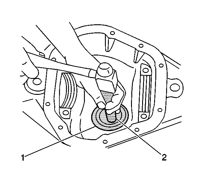
- Using the
J 8092 handle
(2) and the
J 45870 installer
(1),
install the inner pinion bearing cup.
- Determine the selective shim thickness for the drive pinion. Refer to
Pinion Depth Adjustment.
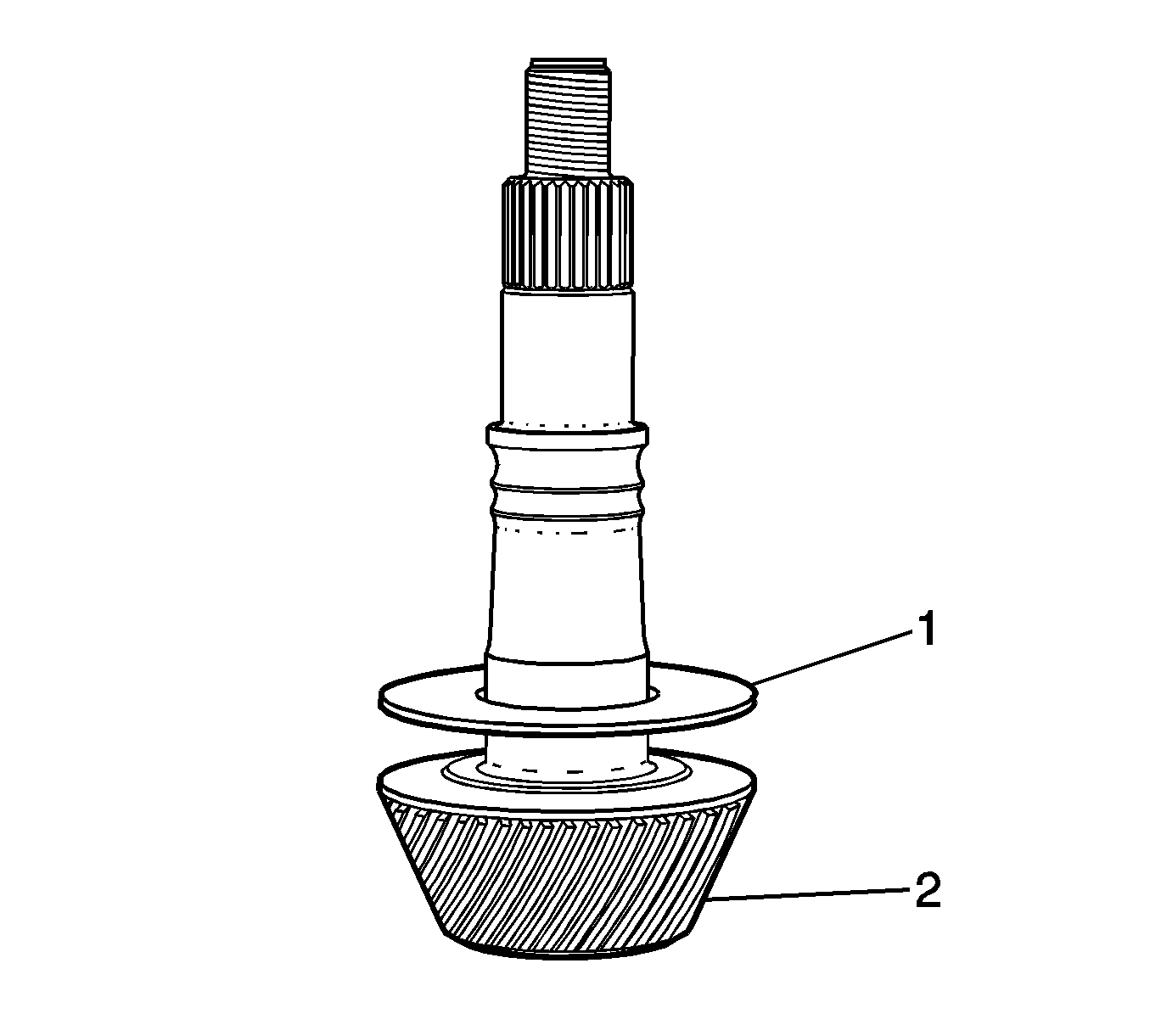
- Install the shim (1) on the differential drive pinion gear (2).
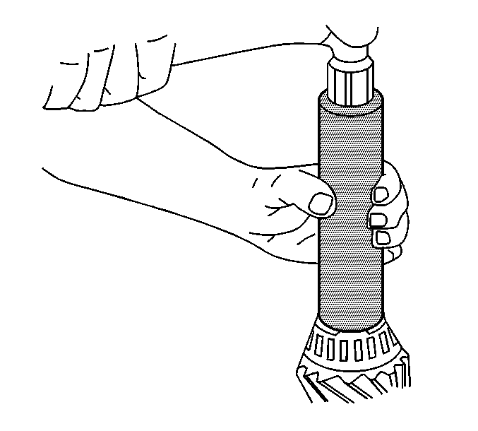
- Using the
J 22828 installer
or the
J 36614 installer
and a hammer, install the inner
pinion bearing until the pinion bearing seats on the drive pinion shim.

- Install a new collapsible spacer.
- Lubricate the pinion bearings with the axle lubricant. Refer to
Fluid and Lubricant Recommendations.
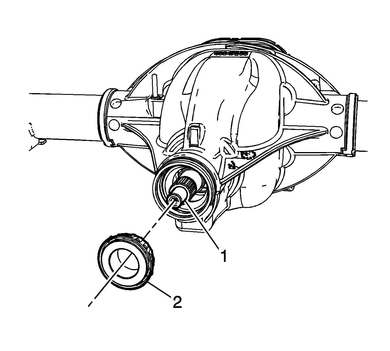
- Install the outer pinion bearing (2) into the differential drive pinion gear (1).
- Install the drive pinion flange/yoke and or oil seal. Refer to
Drive Pinion Flange/Yoke and/or Oil Seal Replacement.

- Using an inch-pound torque wrench, measure the rotating torque of the drive pinion should be between
1.0-2.3 N·m (10-20 lb in) for used bearings and
1.7-3.4 N·m (15-30 lb in) for new bearings.
- If the rotating torque measurement is below
1.0 N·m (10 lb in) for used bearings, or
1.7 N·m (15 lb in) for new bearings, continue to tighten
the pinion nut in small increments, as needed, until the desired rotating torque specificationas are reached as indicated in steps 10 and 11..
- Once the specified torque is obtained, rotate the pinion several times to ensure the bearings have seated.
- Recheck the rotating torque and adjust if necessary.
- Install the differential assembly. Refer to
Differential Replacement.
- Fill the axle with lubricant. Use the proper fluid. Refer to
Rear Axle Lubricant Replacement.
- Remove the support and lower the vehicle.


