GM Service Manual Online
For 1990-2009 cars only
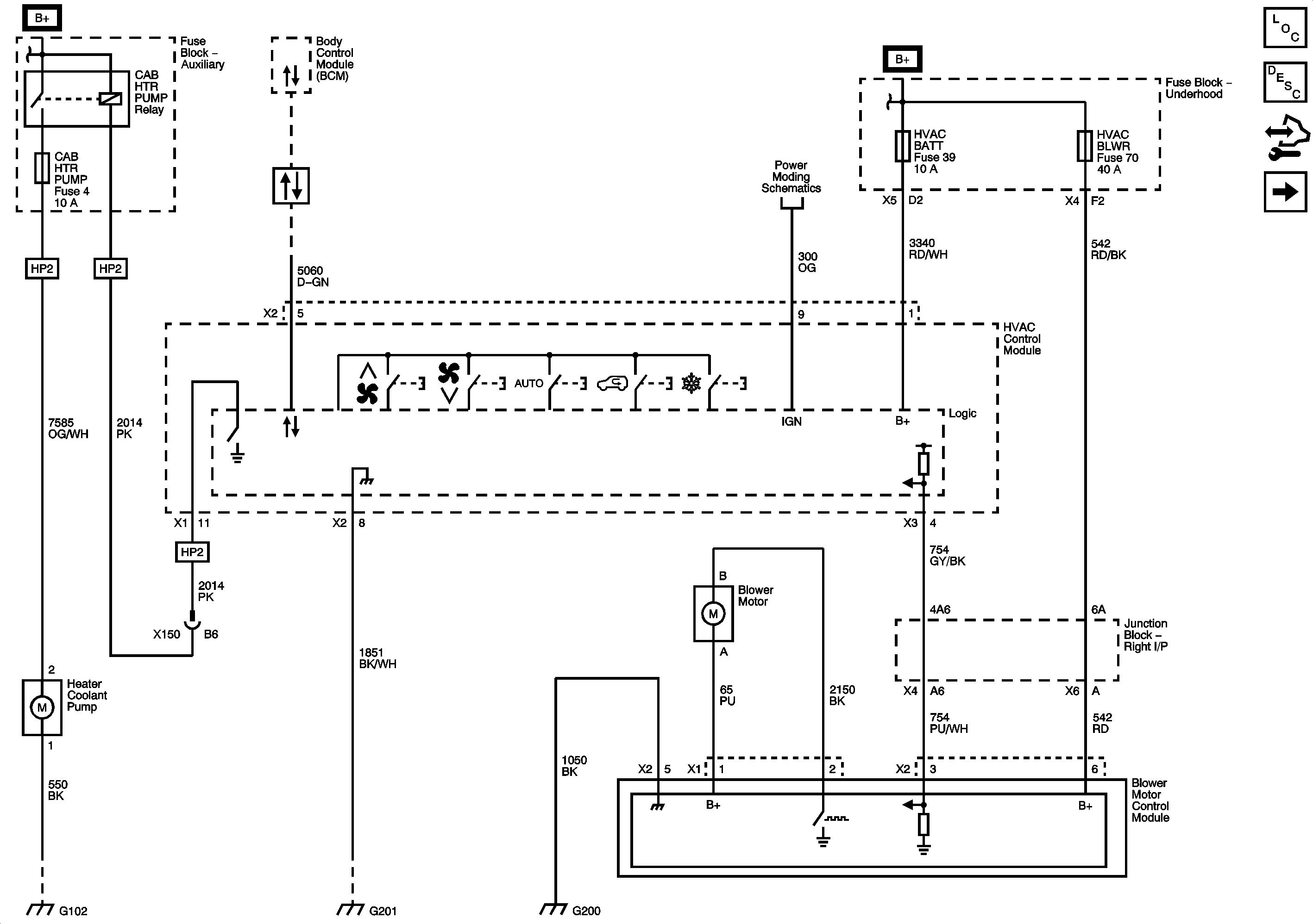
Figure 1:

Module Power, Ground, Serial Data, Front Blower Controls and Hybrid Cabin Heating

Object Number: 1906949  Size: FS
Master Electrical Component List
Air Temperature Description and Operation
Control Module References
Front Mode Controls
ACCM, ACPO, BECM, BECM FAN, CAB HTR PUMP, COOL PUMP, EPS, PIM 1 and PIM 2 Fuses
Data Communication Schematics
Ignition 3 and Accessory Voltage
ECM-BATT, HEADLAMP WASH, HVAC BATT, IPC, LTR, S/ROOF, and TCM-BATT Fuses
ABS-1, ABS 2, HEAVY DUTY ABS, HVAC BLWR, STUD 1, STUD 2, and WFHS Fuses
G102, G104, and G108
G201
G200 - 1 of 2
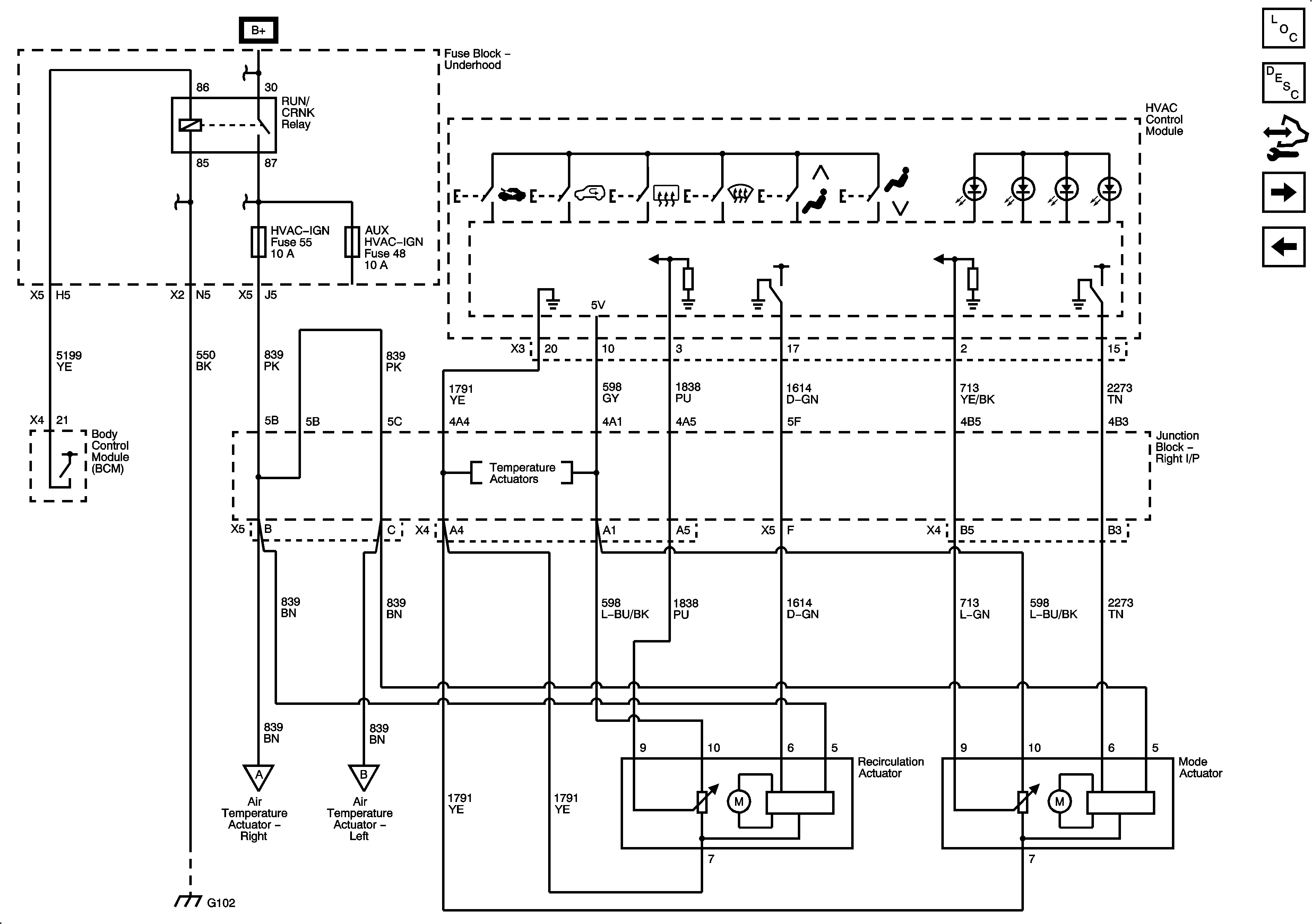
Figure 2:

Front Mode Controls


Object Number: 1906953  Size: FS
Master Electrical Component List
Air Delivery Description and Operation
Control Module References
Front Temperature Controls
Module Power, Ground, Serial Data, Front Blower Controls and Hybrid Cabin Heating
RUN/CRANK Bus - AUX HVAC - IGN and HVAC - IGN Fuses
Front Temperature Controls
G102, G104, and G108
Front Temperature Controls
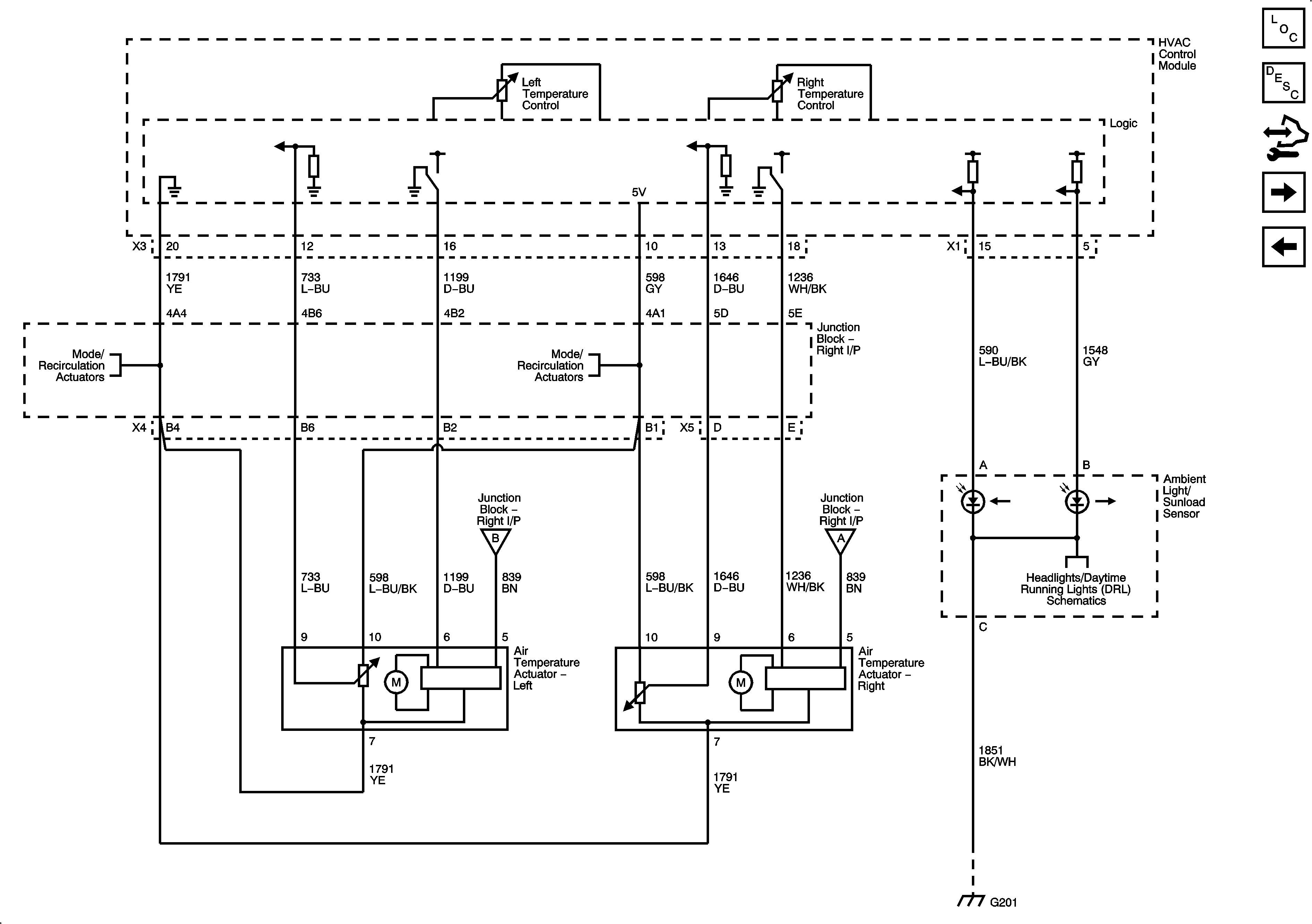
Figure 3:

Front Temperature Controls


Object Number: 1906957  Size: FS
Master Electrical Component List
Air Temperature Description and Operation
Control Module References
Front Temperature Sensors
Front Mode Controls
Front Mode Controls
Front Mode Controls
Front Mode Controls
Front Mode Controls
G201
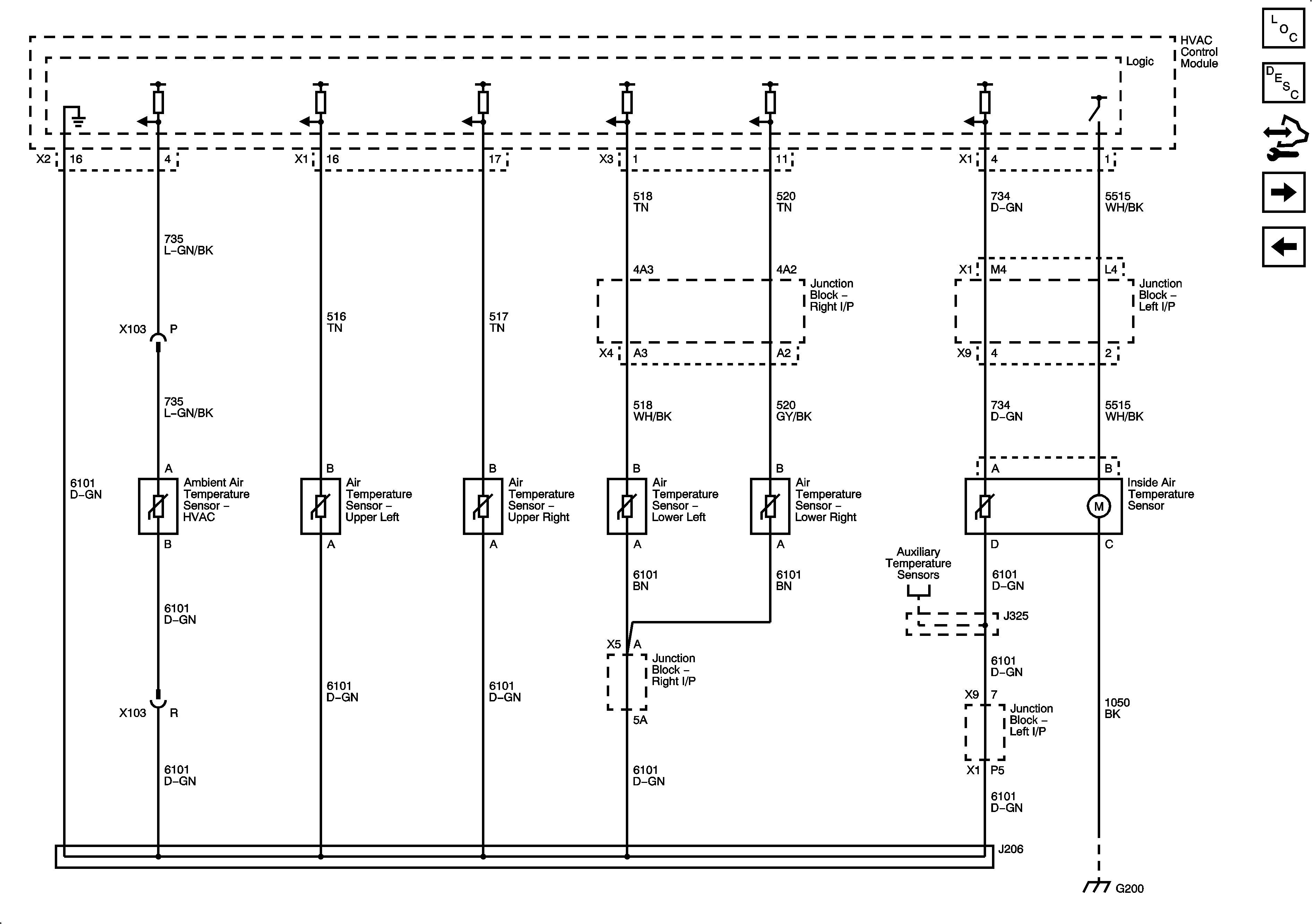
Figure 4:

Front Temperature Sensors


Object Number: 1906961  Size: FS
Master Electrical Component List
Air Temperature Description and Operation
Control Module References
Auxiliary Blower Controls
Front Temperature Controls
G200 - 1 of 2
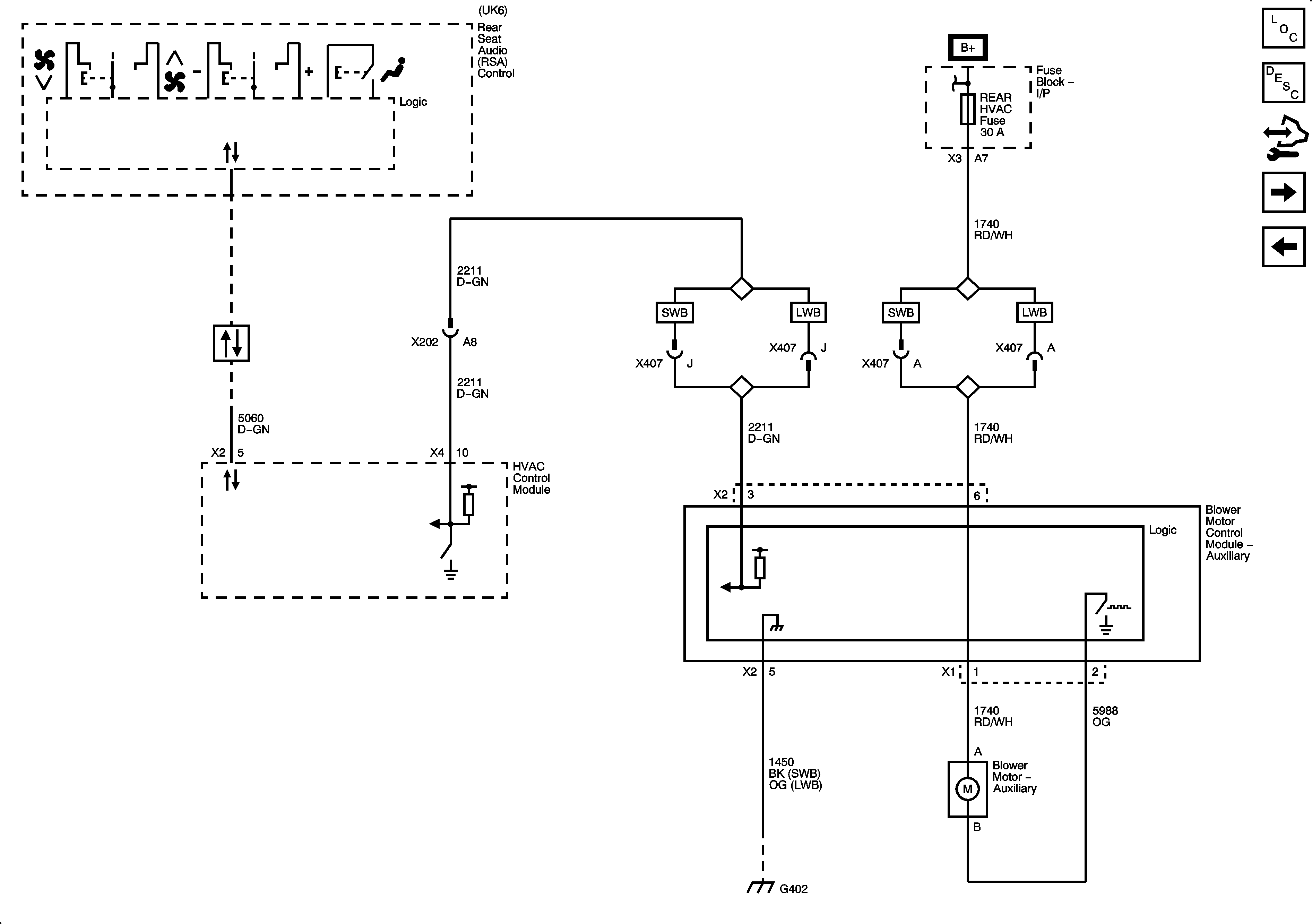
Figure 5:

Auxiliary Blower Controls


Object Number: 1906964  Size: FS
Master Electrical Component List
Air Temperature Description and Operation
Control Module References
Auxiliary Mode and Temperature Controls
Front Temperature Sensors
BCM, COOLED SEATS, CTSY, DDM, DIM, DSM, LBEC 1, MBEC 1, REAR HVAC, and RT STOP TRN Fuses and DRIVER SEAT 2, PASS SEAT 1, and RT DOORS Circuit Breakers
Data Communication Schematics
G402 - E52
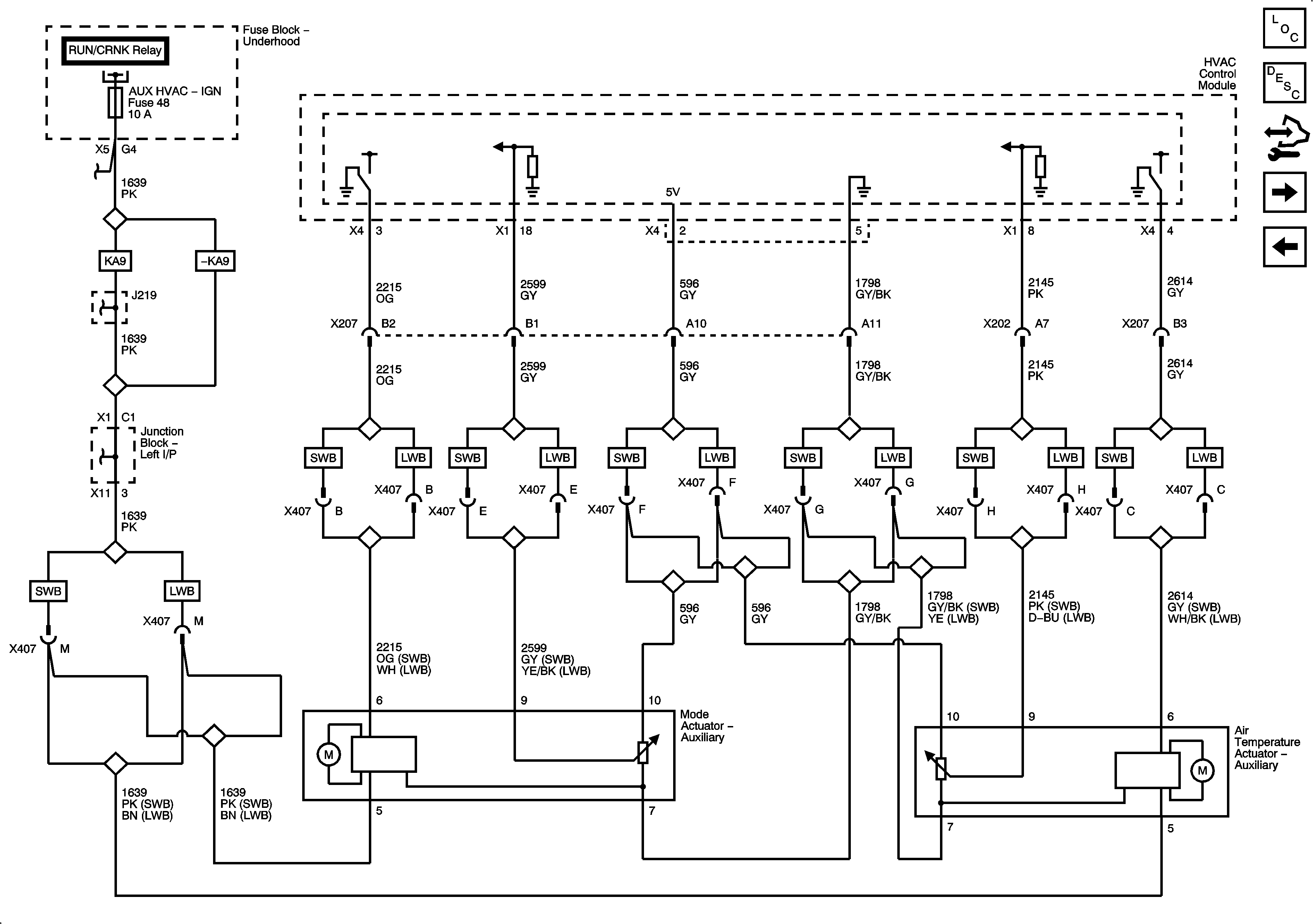
Figure 6:

Auxiliary Mode and Temperature Controls


Object Number: 1906967  Size: FS
Master Electrical Component List
Air Delivery Description and Operation
Control Module References
Auxiliary Temperature Sensors
Auxiliary Blower Controls
Figure 7:

Auxiliary Temperature Sensors


Object Number: 1906970  Size: FS
Master Electrical Component List
Air Temperature Description and Operation
Control Module References
A/C Compressor Controls
Auxiliary Mode and Temperature Controls
Front Temperature Sensors
G200 - 1 of 2
Figure 8:

A/C Compressor Controls


Object Number: 1907171  Size: FS
Master Electrical Component List
Air Temperature Description and Operation
Control Module References
A/C Compressor Controls (HP2)
Auxiliary Temperature Sensors
Data Communication Schematics
A/C CMPRSR, FRT WASH, FUEL PUMP, HORN, and REAR DEFOG and REAR WASH Fuses
G103, G110 and G111
G102, G104, and G108
Figure 9:

A/C Compressor Controls (HP2)


Object Number: 1992587  Size: FS
Master Electrical Component List
Air Temperature Description and Operation
Control Module References
A/C Compressor Controls
ACCM, ACPO, BECM, BECM FAN, CAB HTR PUMP, COOL PUMP, EPS, PIM 1 and PIM 2 Fuses
G201
Data Communication Schematics