For 1990-2009 cars only
Tools Required
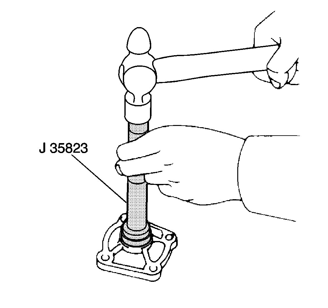
J 35823 Shift Shaft Seal Installer
Removal Procedure
- Remove the assembly from the case.
- Remove the E-clip and the compression spring.
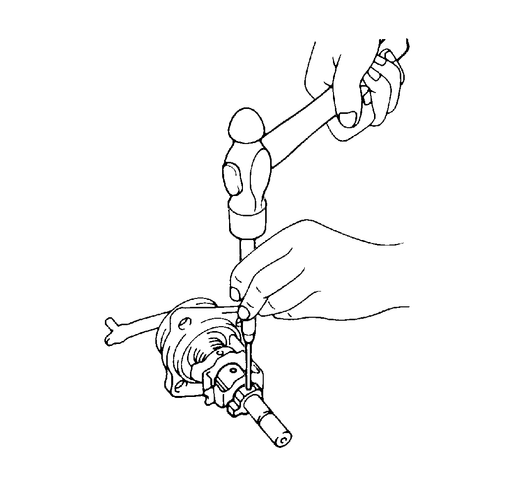
- Using a pin punch and a hammer, driver out the slotted spring pins from the shift inner levers number 1 and number 2.
- Remove the shift inner lever number 2.
- Remove the following components:
- Using a pin punch and a hammer, driver out the slotted spring pin from the select inner lever.
- Remove the following components:
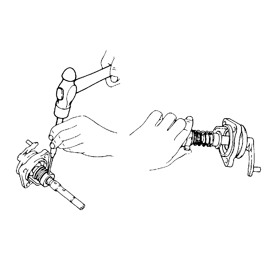
- Remove the snap ring from the lever shaft using two screwdrivers and a hammer.
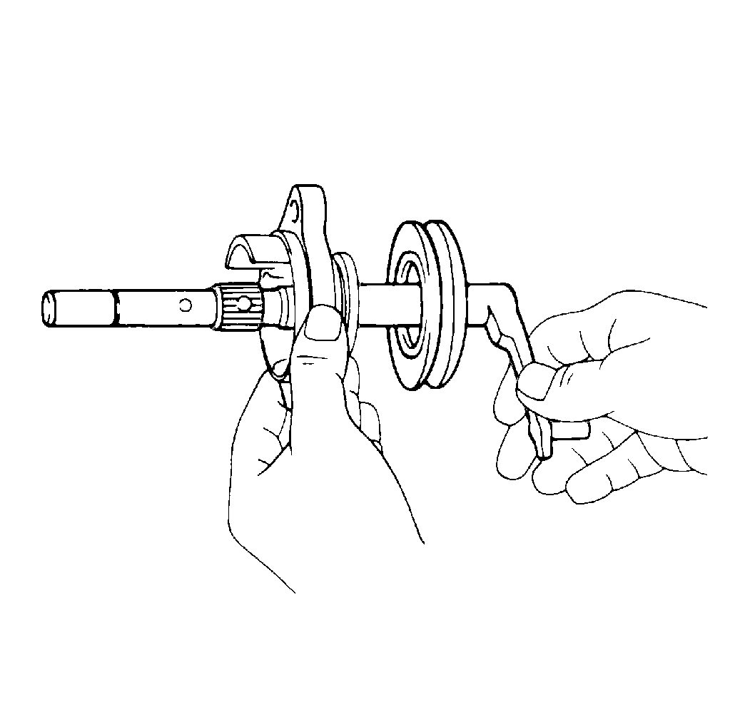
- Remove the lever shaft and boot.
- Remove the shaft seal.
- Inspect the following parts for excessive wear or damage. Replace components as required:

| • | The shift inner lever number 1 |
| • | The shift interlock plate. |

| • | The select inner lever |
| • | The compression spring |
| • | The spring seat |

| • | The lever and boot |
| • | The select inner lever |
| • | The shift inner lever number 1 and number 2 |
| • | The compression spring and seats |
Installation Procedure
- Install the shaft seal using a J 35823 .
- Coat the shaft lightly with GM P/N 1051344.
- Install the following components:
- Install the following components:
- Install the following components:
- Install the spring pin using a pin punch and a hammer.
- Install the number 1 shift inner lever by aligning the interlock plate.
- Install the number 2 shift inner lever.
- Install the slotted pin in the number 2 shift lever using a pin punch and a hammer.
- Install the following components:
- Install the assembly into the case.

Important: Make sure to install the boot in the correct direction. Position the air bleed of the boot downward.
| • | The boot |
| • | The lever shaft |
| • | The snap ring |
| • | The spring seat |

| • | The compression spring |
| • | The select inner lever |

| • | The compression spring |
| • | The seat |
| • | The E-clip |
