Lower Control Arm Replacement RWD
Tools Required
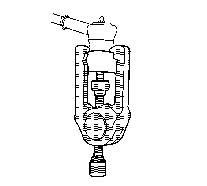
J 23742 Ball Joint Separator
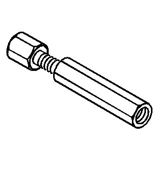
Removal Procedure
- Remove the coil spring. Refer to Front Coil Springs Replacement .
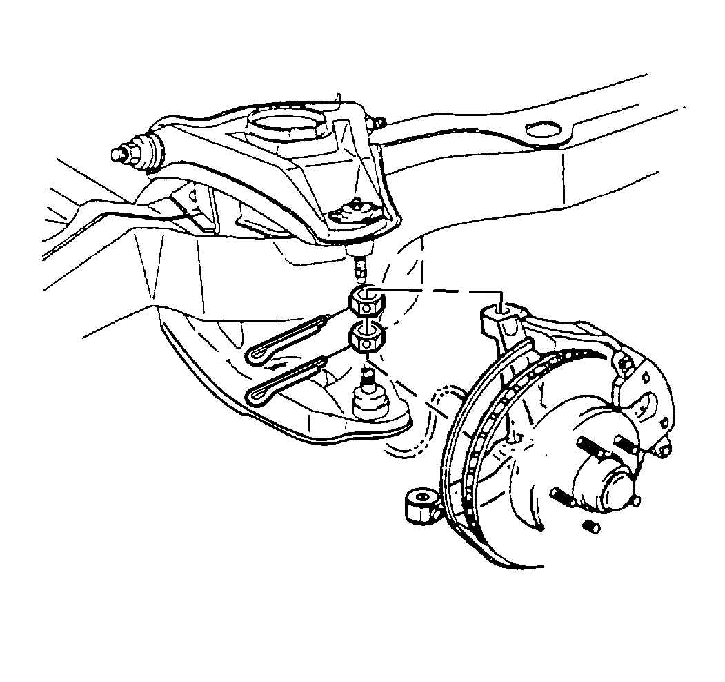
- Remove the lower ball joint cotter pin and the retaining nut.
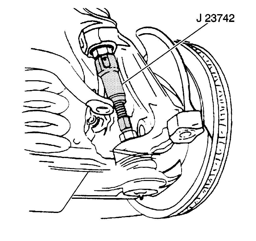
- Disconnect the lower ball joint from the steering knuckle using J 23742 .
- Remove the lower control arm.
Installation Procedure
- Connect the lower ball joint to the steering knuckle.
- Install the lower ball joint retaining nut.
- Install a new cotter pin. Tighten the nut up to an additional 1/6 amount in order to insert the cotter pin through the lower ball joint stud. Bend the cotter pin ends flat against the nut.
- Install the coil spring. Refer to Front Coil Springs Replacement .
- Check the front wheel alignment. Refer to Wheel Alignment Measurement in Wheel Alignment.
Make sure the lower ball joint is properly seated into the steering knuckle.
Notice: Use the correct fastener in the correct location. Replacement fasteners must be the correct part number for that application. Fasteners requiring replacement or fasteners requiring the use of thread locking compound or sealant are identified in the service procedure. Do not use paints, lubricants, or corrosion inhibitors on fasteners or fastener joint surfaces unless specified. These coatings affect fastener torque and joint clamping force and may damage the fastener. Use the correct tightening sequence and specifications when installing fasteners in order to avoid damage to parts and systems.
Tighten
Tighten the lower ball joint nut to 125 N·m (90 lb ft).
Lower Control Arm Replacement AWD
Tool Required
| • | J 24319-B Steering Linkage and Tie Rod Puller |
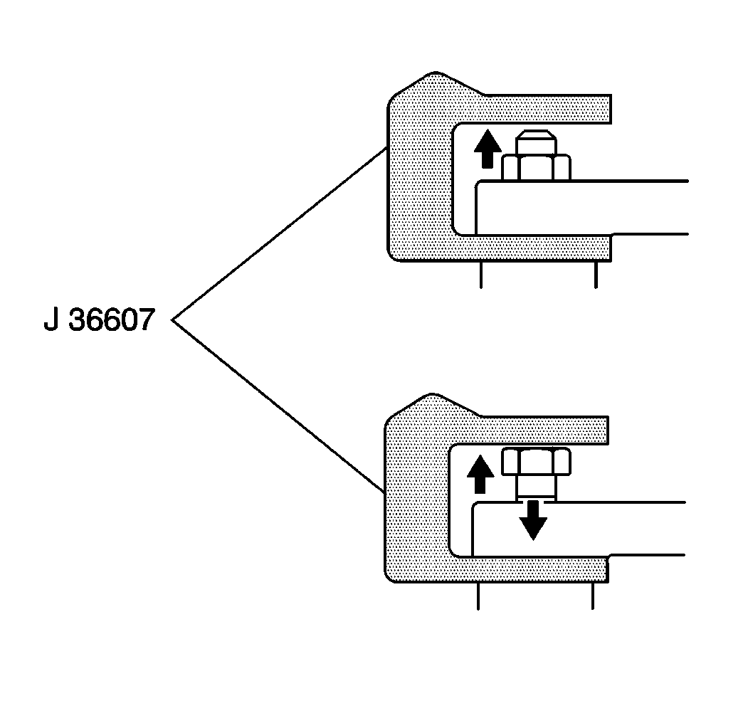
| • | J 36607 Upper Ball Joint Separator |
| • | J 45859 Axle Remover |
Removal Procedure
- Raise the vehicle. Refer to Lifting and Jacking the Vehicle in General Information.
- Remove the tire and wheel. Refer to Tire and Wheel Removal and Installation in Tires and Wheels.
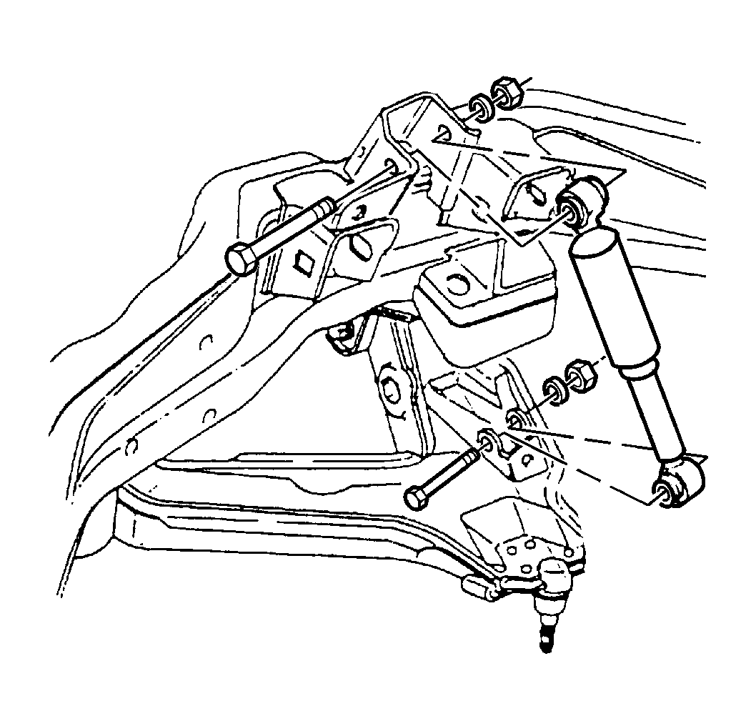
- Remove the torsion bar. Refer to Torsion Bar Replacement .
- Remove the stabilizer shaft link. Refer to Stabilizer Shaft Link Replacement .
- Remove the shock absorber lower mounting bolt.
- Compress the shock absorber.
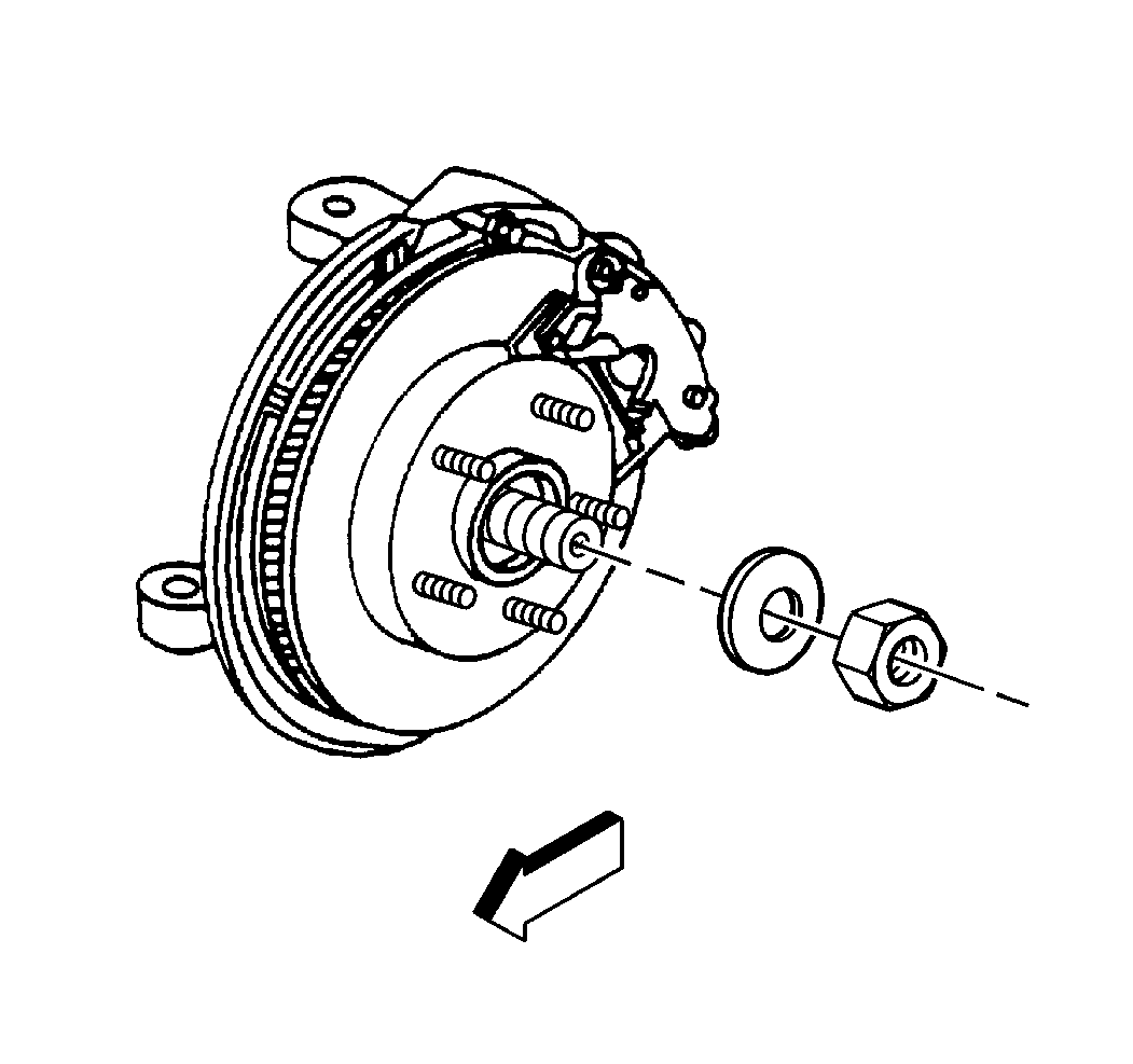
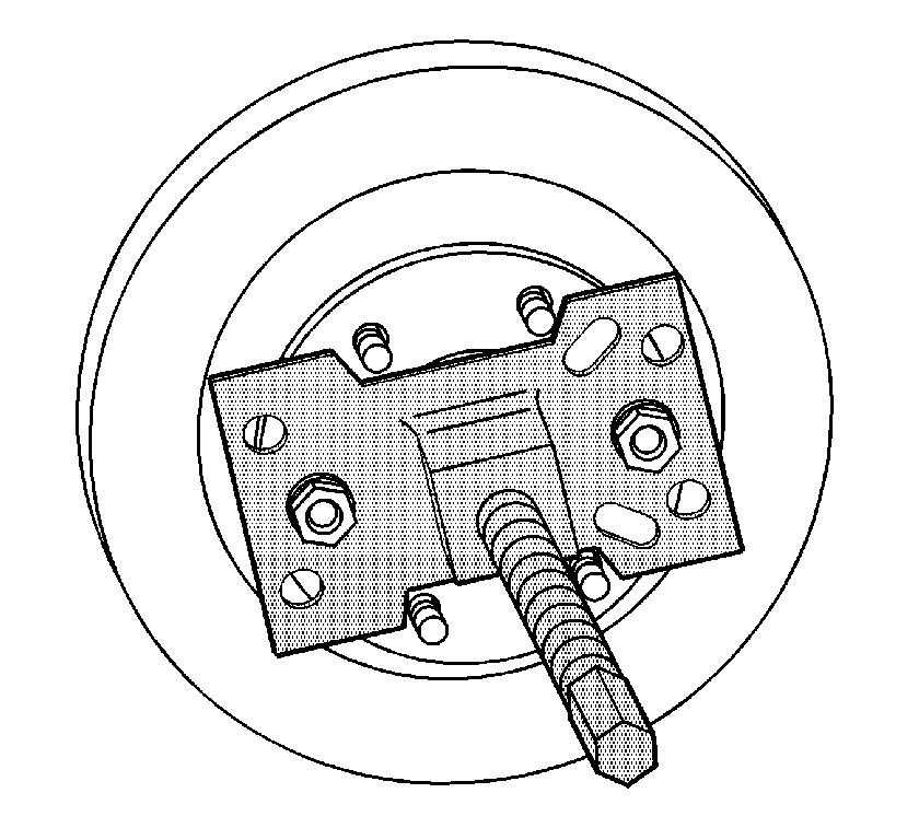
- Remove the rotor. Refer to Front Brake Rotor Replacement in Disc Brakes.
- Remove the wheel drive shaft retaining nut and the washer from the wheel hub and bearing.
- Disengage the wheel drive shaft from the wheel hub and bearing using J 45859 .
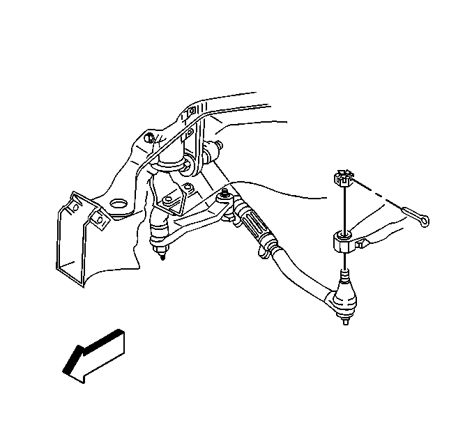
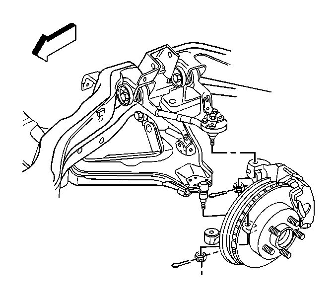
- Remove the outer tie rod cotter pin and retaining nut.
- Remove the outer tie rod from the steering knuckle using the J 24319-B .
- Disconnect the wheel speed sensor electrical connector.
- Remove the wheel speed sensor bracket retaining bolts at the frame and upper control arm.
- Disconnect the wheel speed sensor wiring harness clips form the upper control arm.
- Remove the upper ball joint cotter pin and retaining nut.
- Install the J 36607 to the upper control arm and steering knuckle.
- Disconnect the upper control arm from the steering knuckle using the J 36607 .
- Remove the lower ball joint cotter pin and retaining nut.
- Using a pry bar, placed on top of the upper control arm and on the bottom of the frame, pry downward.
- With the aid of a helper, carefully hammer on the steering knuckle in the area of the lower ball joint stud in order to release the stud from the steering knuckle.
- Remove the steering knuckle and wheel hub and bearing.
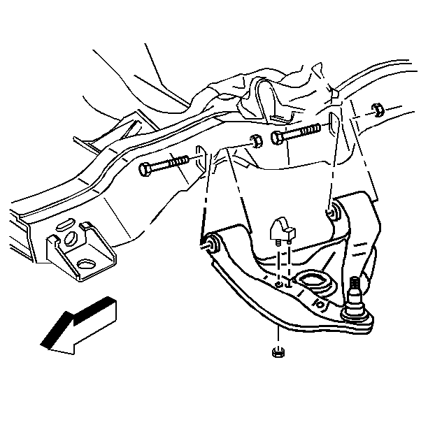
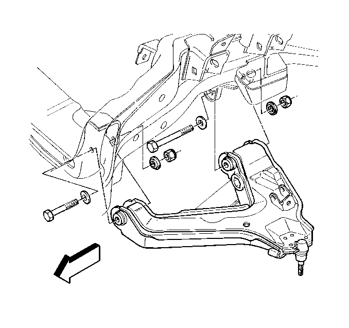
- Remove the lower control arm mounting nuts and the washer.
- Remove the lower control arm mounting bolts.
- Remove the lower control arm from the vehicle.
- Remove the lower control arm brace from the lower control arm.
Installation Procedure
- Install the lower control arm brace to the lower control arm.
- Install the lower control arm to the crossmember and frame bracket.
- Install the lower control arm bolts in the proper direction.
- Install the new nuts and the washers.
- Tighten the lower control arm nuts and bolts with the front suspension loaded.
- Tighten the lower control arm front mounting nuts to 133 N·m (98 lb ft).
- Tighten the lower control arm rear mounting nuts to 133 N·m (98 lb ft).
- Install the steering knuckle and the wheel hub and bearing to the lower ball joint.
- Install the lower ball joint retaining nut.
- Connect the upper ball joint to the steering knuckle.
- Install the upper ball joint retaining nut.
- Install new cotter pins to the upper and lower ball joints. Tighten the nut up to an additional 1/6 amount in order to insert the cotter pin through the upper and lower ball joint studs. Bend the cotter pin ends flat against the nut.
- Connect the wheel speed sensor wiring harness clips to the upper control arm.
- Install the wheel speed sensor wiring harness bracket retaining bolts at the steering knuckle and the frame.
- Connect the wheel speed sensor electrical connector.
- Connect the outer tie rod to the steering knuckle.
- Install the outer tie rod retaining nut and cotter pin.
- Install the wheel drive shaft washer and the retaining nut to the wheel hub and bearing.
- Install the rotor. Refer to Front Brake Rotor Replacement in Disc Brakes.
- Install the shock absorber lower mounting bolt.
- Install the stabilizer shaft link. Refer to Stabilizer Shaft Link Replacement .
- Install the torsion bar. Refer to Torsion Bar Replacement .
- Install the tire and wheel. Refer to Tire and Wheel Removal and Installation in Tires and Wheels.
- Lower the vehicle.
- Check the front wheel alignment. Refer to Wheel Alignment Measurement in Wheel Alignment.
Important: Install the front leg of the lower control arm to the crossmember before installing the rear leg to the frame bracket.
Notice: Use the correct fastener in the correct location. Replacement fasteners must be the correct part number for that application. Fasteners requiring replacement or fasteners requiring the use of thread locking compound or sealant are identified in the service procedure. Do not use paints, lubricants, or corrosion inhibitors on fasteners or fastener joint surfaces unless specified. These coatings affect fastener torque and joint clamping force and may damage the fastener. Use the correct tightening sequence and specifications when installing fasteners in order to avoid damage to parts and systems.
Important: Tighten the nuts with the control arm at Z height. Refer to Trim Height Inspection in Suspension General Diagnosis.
Tighten
Tighten
| • | Tighten the upper ball joint retaining nut to 98 N·m (72 lb ft). |
| • | Tighten the lower ball joint retaining nut to 128 N·m (95 lb ft). |
Tighten
Tighten the outer tie rod retaining nut to 49 N·m (36 lb ft).
Tighten
Tighten the wheel drive shaft retaining nut to 200 N·m (147 lb ft).
Tighten
Tighten the lower shock mounting bolt to 62 N·m (42 lb ft).
