Circuit Description
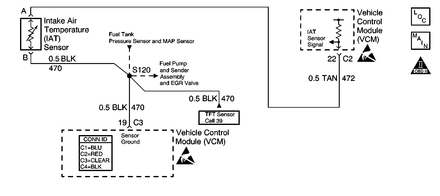
The intake air temperature (IAT) sensor is a thermistor. The control module supplies the IAT sensor a reference voltage on the IAT sensor signal circuit and a ground circuit. When the IAT sensor resistance is high, indicating a cold sensor, the IAT sensor signal voltage remains near the supplied voltage and decreases the signal voltage as the sensor warms. The control module monitors the IAT sensor signal circuit in order to calculate the temperature of the air entering the engine.
This DTC is designed to detect an IAT sensor signal voltage higher than the possible range of a normally operating IAT sensor.
Conditions for Running the DTC
| • | No active engine coolant temperature (ECT) sensor DTCs |
| • | No active VSS DTCs |
| • | No active mass air flow (MAF) sensor DTCs |
| • | The vehicle speed is less than 2 mph (3 km/h) |
| • | The MAF is less than 250 g/s |
| • | The engine coolant temperature is more than 85°C (186°F) |
| • | The engine run time is more than 100 seconds |
Conditions for Setting the DTC
The IAT voltage is more than 4.9 V for more than 5 seconds.
Action Taken When the DTC Sets
| • | The control module illuminates the malfunction indicator lamp (MIL) if a failure is detected during 2 consecutive key cycles. |
| • | The control module sets the DTC and records the operating conditions at the time the diagnostic failed. The failure information is stored in the scan tool Freeze Frame/Failure Records. |
Conditions for Clearing the MIL or DTC
| • | The control module turns OFF the MIL after 3 consecutive drive trips when the test has run and passed. |
| • | A history DTC will clear if no fault conditions have been detected for 40 warm-up cycles. A warm-up cycle occurs when the coolant temperature has risen 22°C (40°F) from the startup coolant temperature and the engine coolant reaches a temperature that is more than 70°C (158°F) during the same ignition cycle. |
| • | Use a scan tool in order to clear the DTCs. |
Diagnostic Aids
The IAT sensor indicates the temperature of the ambient air which is entering the throttle body. The IAT temperature should read very close to the temperature of the outside air. The IAT sensor temperature should rise gradually as the engine warms up and the underhood temperature increases. If DTC P1111 is set, the problem is intermittent. Inspect for an open in the IAT sensor circuit. This may be accomplished by moving the vehicle control module (VCM) harness at various locations and monitoring the IAT temperature or IAT voltage on the scan tool. If the voltage varies, look for an open in the area of the harness that caused the variance. Also, a sensor may become skewed or mis-scaled. The Temperature vs. Resistance Value Table will help in order to detect a skewed sensor. Refer to Temperature Versus Resistance .
An intermittent may be caused by any of the following conditions:
| • | A poor connection |
| • | Rubbed through wire insulation |
| • | A broken wire inside the insulation |
Thoroughly inspect any circuitry that is suspected of causing the intermittent complaint. Refer to Testing for Intermittent Conditions and Poor Connections in Wiring Systems.
If a repair is necessary, refer to Wiring Repairs or Connector Repairs in Wiring Systems.
Test Description
The numbers below refer to the step numbers on the diagnostic table.
Important: Use the same diagnostic test equipment for all the measurements.
-
If the IAT sensor circuit voltage measures more than 4.90 volts, the conditions for the DTC are still present, and the problem is not intermittent.
-
This test will bypass the IAT sensor and will confirm that the IAT signal circuit and the sensor ground circuit to the VCM are sound. Grounding the signal circuit will provide a low voltage input to the VCM. The VCM should recognize this low voltage and indicate a high IAT temperature.
-
This test determines if the IAT sensor signal circuit is okay. If the scan tool does not indicate a high temperature, the IAT signal circuit is open.
Step | Action | Value(s) | Yes | No |
|---|---|---|---|---|
1 | Did you perform the Powertrain On-Board Diagnostic (OBD) System Check? | -- | ||
Is the IAT sensor voltage more than the specified value? | 4.90 V | |||
Does the scan tool display an IAT sensor voltage less than the specified value? | 0.82 V | |||
Jumper the IAT Sensor Signal circuit to a known good ground. Does the scan tool display an IAT sensor voltage less than the specified value? | 0.82 V | |||
5 | Check the voltage between the IAT sensor signal circuit and a known good ground with a J 39200 DMM. Is the voltage more than the specified value? | 5.20 V | ||
6 | The DTC is intermittent. Are any additional DTCs stored? | -- | Go to the applicable DTC table | Go to Diagnostic Aids |
7 | Check the sensor connector and the VCM connector for a poor connection. Did you find a problem? | -- | ||
8 | Check the IAT sensor ground circuit for an open or poor connection between the IAT sensor and the VCM. Did you find a problem? | -- | ||
9 | Check the IAT sensor signal circuit for an open or poor connection between the IAT sensor and the VCM. Did you find a problem? | -- | ||
10 | Repair the short to voltage in the IAT sensor signal circuit. Refer to Wiring Repairs in Wiring Systems. Is the action complete? | -- | -- | |
11 | Repair the circuit as necessary. Refer to Wiring Repairs or Connector Repairs in Wiring Systems. Is the action complete? | -- | -- | |
12 | Replace the IAT sensor. Refer to Intake Air Temperature Sensor Replacement . Is the action complete? | -- | -- | |
13 |
Important: The replacement VCM must be programmed. Replace the VCM. Refer to VCM Replacement/Programming . Is the action complete? | -- | -- | |
14 |
Does the scan tool indicate the diagnostic Passed? | -- | ||
15 | Does the scan tool display any additional undiagnosed DTCs? | -- | Go to the applicable DTC table | System OK |
