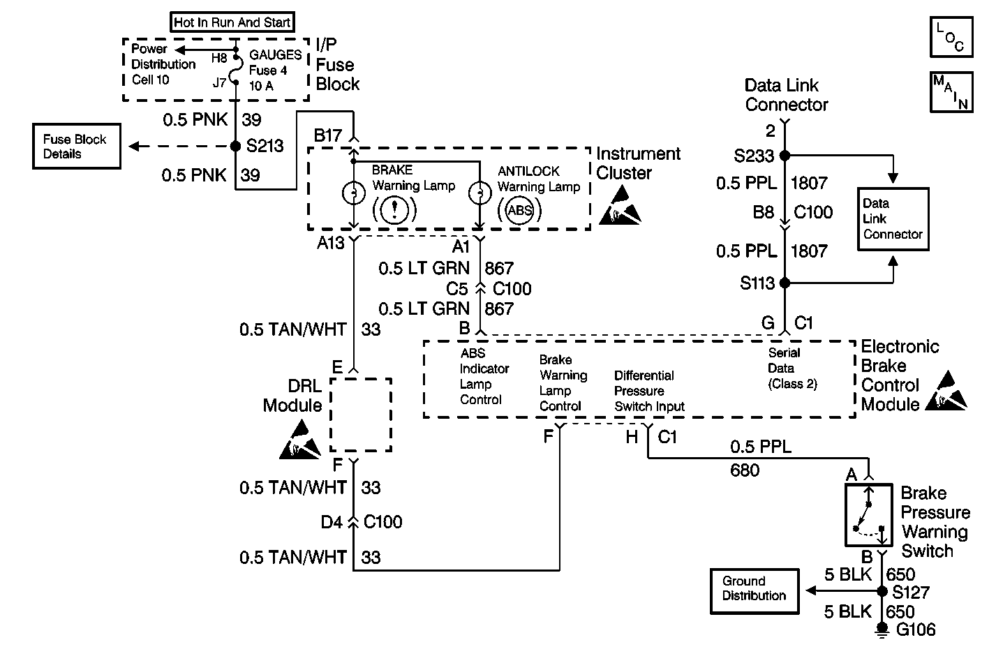
Circuit Description
The EBCM controls the ABS indicator lamp illumination by supplying a ground to the EBCM 10-way terminal B. When the vehicle is started or the ignition is turned to the RUN position, the ABS indicator should illuminate for two seconds and turn off.
Diagnostic Aids
If the ABS indicator lamp is off constantly, an open or short to voltage in the lamp circuit is present between the instrument panel and the ABS indicator relay ground (this includes the ABS indicator relay contacts). Also check for an open instrument cluster fuse or an open ABS indicator lamp.
Test Description
The numbers below refer to the steps in the diagnostic table:
-
This step tests for ignition voltage up to the EBCM harness connector.
-
This step uses a voltage check to tell if there is a good ground path through terminal B in the 2-way harness connector. The ground supplied through terminal B is used internal to the EBCM to control the ABS indicator lamp through terminal B in the 10-way EBCM connector.
-
After the power and ground circuits have been verified, this step uses the EBCM self test to determine if the problem is intermittent or if the EBCM is faulty.
-
The voltage check in step 3 failed. This step goes further to check for the proper voltage from CKT 39 at the input to the instrument cluster.
-
This step checks for continuity in CKT 867, and decides between an open in CKT 867, or a fault internal to the instrument cluster.
-
The voltage check in step 6 failed. This step checks for a short to ground in CKT 39 as a potential cause.
-
This step uses a resistance check of the EBCM ground circuit to decide between an open ground in CKT 150 or internal to the EBCM.
Step | Action | Value(s) | Yes | No |
|---|---|---|---|---|
1 | Was the Diagnostic System Check performed? | -- | Go to Step 2 | |
2 | Check the condition of the ABS indicator lamp bulb. Is the bulb OK? | Go to Step 3 | Go to Step 10 | |
Is the voltage measurement within the specified range? | 10-15V | Go to Step 4 | Go to Step 6 | |
Is the voltage measurement within the specified range? | 10-15V | Go to Step 5 | Go to Step 9 | |
Did the ABS indicator lamp turn on for 2 seconds then go out? | -- | Malfunction is intermittent. Go to Diagnostic Aids | Go to Step 11 | |
Is the voltage measurement within the specified range? | 10-15V | Go to Step 7 | Go to Step 8 | |
Is the resistance measurement within the specified range? | 0-2ohms | Go to Instrument Cluster Diagnosis | Go to Step 12 | |
Is the GAUGES fuse open? | -- | Go to Step 13 | Go to Step 14 | |
Using a J 39200 , measure the resisatnce between terminal B in the 2-way EBCM harness connector and ground. Is the resistance measurement within the specified range? | 0-2ohms | Go to Step 11 | Go to Step 15 | |
10 | Replace the ABS indicator lamp. Refer to Instrument Cluster Bulb Replacement . Is the repair complete? | -- | -- | |
11 | Replace the EBCM. Refer to Electronic Brake Control Module Replacement . Is the repair complete? | -- | -- | |
12 | Repair the open or the high resistance in CKT 867. Is the repair complete? | -- | -- | |
13 | Repair the short to ground in CKT 39. Refer to Wiring Systems. Is the repair complete? | -- | -- | |
14 | Repair the open or high resistance in CKT 39. Refer to Wiring Systems. Is the repair complete? | -- | -- | |
15 | Repair the open in CKT 650. Refer to Wiring Systems. Is the repair complete? | -- | -- |
