TV SYSTEM DIAG.-ALL A/T EXCEPT THM 180,350,400

MODEL AND YEAR: ALL HYDRAMATIC BUILT THROTTLE VALVE CONTROLLED TRANSMISSIONS/TRANSAXLES (EXCEPT THM 180, THM 350, THM 400)
This bulletin covers background and diagnosis information on the Throttle Valve (T.V.) system and applies to all THM transaxles/transmissions, except the THM 180, 350, and 400 models. Included are revised procedures using a pressure gage during adjustment/diagnosis, inspection of components and other items not yet covered in the Service Manual.
BACKGROUND
Throttle valve (T.V.) pressure controls the shift pattern and the amount of hydraulic line pressure used to apply clutches and bands. (NOTE: The THM 440-T4 T.V. cable controls shift timing, not shift feel, line pressure is not directly affected by T.V. cable setting.) If proper line pressure is not available, excess slippage may occur during the shift. If the T.V. cable is tailored in an effort to modify shift pattern/feel, this misadjustment can result in transmission/transaxle failure.
IMPORTANT: Do not attempt to correct a condition by changing the T.V. cable setting from its proper adjustment. Apparent improvements from T.V. cable "tailoring" indicate a need for further diagnosis into the real cause of a condition (such as engine performance, the control valve, governor or servo assemblies, etc.).
Dealer personnel and customers should know that certain types of heavy duty or high performance vehicles have transmissions calibrated to provide crisp, firm shifts for durability/performance. Once again, the T.V. cable must not be tailored in an effort to modify shift pattern/feel on these applications.
IMPORTANT: Make sure engine fuel, electrical and mechanical systems are performing properly before attempting transmission/transaxle diagnosis. For example, a fouled fuel injector, cracked spark plug, damaged spark plug wire or vacuum leak can affect transmission/transaxle performance.
The T.V. system may cause one or more of the following conditions:
-- Delayed or harsh upshifts -- Early and slipping upshifts -- High or low line pressure (except the THM 440-T4) -- No upshifts -- Chatters on takeoff -- 1-2 shift at full throttle only -- No full throttle or part throttle detent downshifts -- Intermittent second gear starts
The above listed conditions may be caused by a T.V. cable that is:
-- Improperly adjusted -- Kinked or binding -- Disconnected -- Broken -- Wrong part
CAUTION:
To avoid possible personal injury and/or damage to the vehicle, the following diagnosis procedure must be performed with the vehicle parking brake properly applied.
DIAGNOSIS Inspect
- T.V. cable for correct part number, listed in the parts catalog.
- T.V. cable for kinked, binding, disconnected or broken condition.
Install or Connect
- Line pressure gage. - Engine tachometer. - Warm up engine to normal operating temperature. - Run engine at 1000 rpm. - With gear selector in "Park", note oil pressure. (NOTE:Remaining steps do not apply to the THM 180, 350, 400 or 440-T4. Refer to the appropriate Service Manual for line pressure diagnosis procedures.) - Place gear selector in "Drive". Oil pressure should be equal or not more than 10 psi (69 kPa) higher than in "Park". - Check the T.V. system's line pressure regulation by manually pulling the T.V. cable its full length of travel and reading gage. Do not increase the engines throttle opening during test.
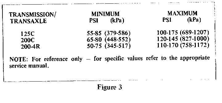
Oil pressure should steadily increase as cable is pulled out and decrease smoothly as cable is returned to original position. Refer to chart for pressure ranges.
TRANSMISSION/ MINIMUM MAXIMUM TRANSAXLE PSI (kPa) PSI (kPa)
125C 55-85 (379-586) 100-175(689-1207) 200C 65-80(448-552) 120-145(827-1000) 200-4R 50-75(345-517) 110-170(758-1172) 700-R4 55-75(379-517) 115-200(793-1379)
T.V. Pressure Range Chart
NOTE: For reference only -- for specific valves refer to the appropriate Service Manual.
If oil pressure does not increase or gage reading bounces unsteadily, inspect the throttle lever and bracket assembly on the control valve assembly. Check that the T.V. exhaust valve lifter rod is not distorted and not binding in the control valve assembly or spacer plate. The T.V. exhaust check ball must move up and down as the lifter does. Also, be sure the lifter spring holds the lifter rod up against the bottom of the control valve assembly. Make sure the T.V. plunger does not stick at any position of travel.
-Check T.V. exhaust valve lifter rod and check ball ("fail-safe") system. With engine at idle, disconnect T.V. cable at throttle linkage. Line pressure should increase to maximum. If line pressure does not increase, inspect the parts as described above.
-Stop engine for at least 30 seconds to take T.V. system out of "fail-safe" mode. Connect T.V. cable, adjust according to the appropriate Service Manual, and repeat line pressure checks in "Park" and "Drive" ranges. If T.V. system does not come out of "fail-safe" mode (pressure remains high), inspect the parts as described above.
General Motors bulletins are intended for use by professional technicians, not a "do-it-yourselfer". They are written to inform those technicians of conditions that may occur on some vehicles, or to provide information that could assist in the proper service of a vehicle. Properly trained technicians have the equipment, tools, safety instructions and know-how to do a job properly and safely. If a condition is described, do not assume that the bulletin applies to your vehicle, or that your vehicle will have that condition. See a General Motors dealer servicing your brand of General Motors vehicle for information on whether your vehicle may benefit from the information.
