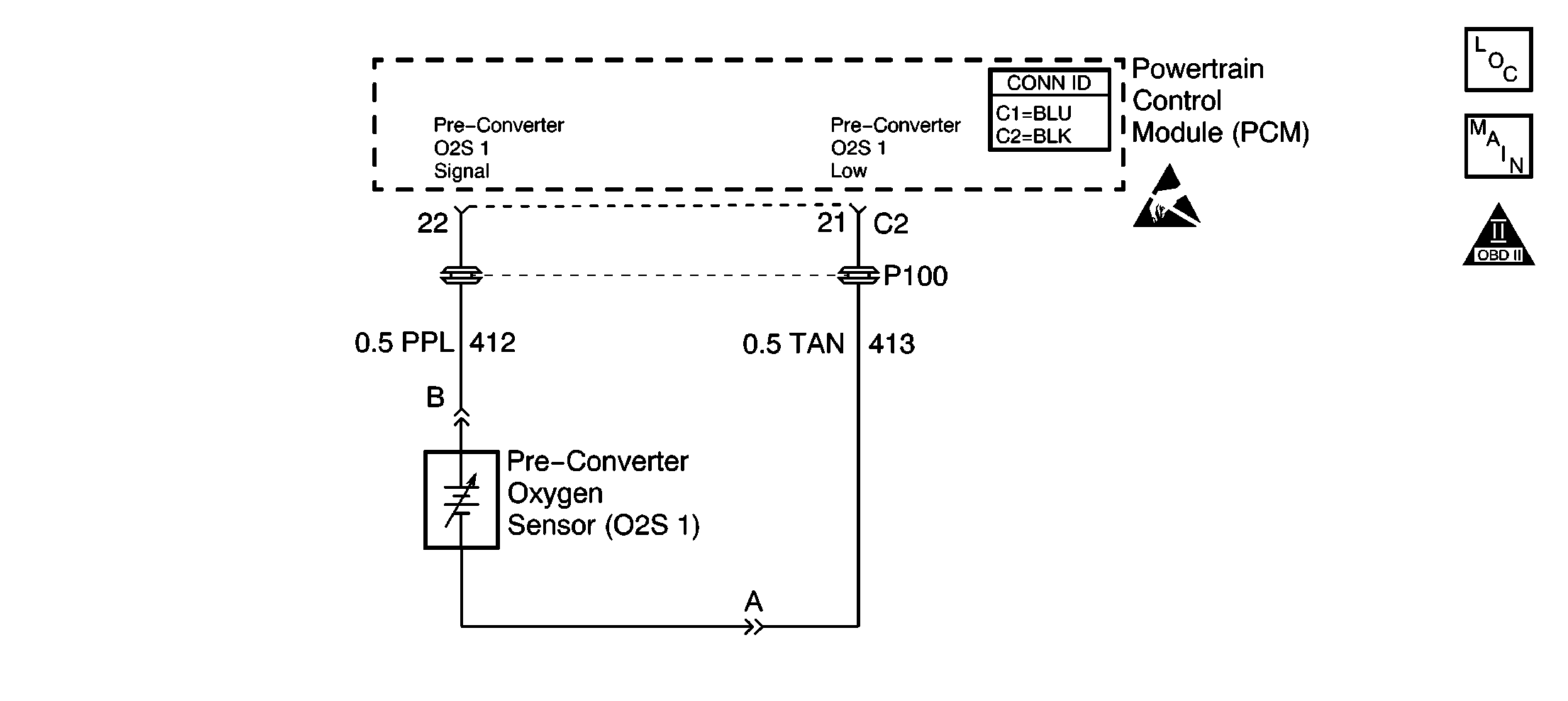
Circuit Description
The Powertrain Control Module(PCM) supplies a voltage of about 0.45 volt between the oxygen sensor (O2S 1) signal and the ground circuit. The O2S 1 varies the voltage within a range of about 1 volt if the exhaust is rich, down through about 0.10 volt if the exhaust is lean.
The sensor is like an open circuit and produces no voltage when below 315°C (600°F). An open sensor circuit or a cold sensor causes an Open Loop operation.
Do not attempt to repair the oxygen sensor. Replace the entire O2S 1 assembly if the following conditions exist:
| • | Any damaged wiring |
| • | A damaged electrical connector |
| • | Any damaged terminals |
Conditions For Running The DTC
| • | The following DTCs are not set: P0105, P0107, P0108, P0112, P0113, P0117, P0118, P0122, P0123, P0171, P0201, P0202, P0203, P0204, P0335, P0440, P0442, P0446, P0506, P0507, P0601, P0602, or P1441. |
| • | The air flow is more than 3 g/s. |
| • | The engine coolant temperature (ECT) is more than 70°C (158°F). |
| • | The engine is operating in Closed Loop. |
| • | The throttle position (TP) angle is between 5 percent and 50 percent. |
| • | The engine has met the above conditions for 30 seconds. |
Conditions For Setting The DTC
| • | The O2S 1 voltage is more than 946 mV for 50 seconds. |
| OR: |
| • | The O2S 1 voltage is more than 1042 mV for 50 seconds while in deceleration mode. |
Action Taken When the DTC Sets
| • | The Malfunction Indicator Lamp (MIL) will illuminate after 2 consecutive ignition cycles in which the diagnostic runs with the fault active. |
| • | The PCM will record the operating conditions at the time that the diagnostic fails. This information will store in the Freeze Frame and Failure Records buffers. |
| • | A history DTC stores. |
| • | The vehicle will operate in an Open Loop operation. |
Conditions for Clearing the MIL/DTC
| • | The MIL will turn off after 3 consecutive ignition cycles in which the diagnostic runs without a fault. |
| • | A history DTC will clear after 40 consecutive warm up cycles without a fault. |
| • | Use a scan tool to clear the DTCs. |
Diagnostic Aids
The DTC P0132 or rich exhaust is likely caused by one of the following conditions:
| • | The fuel system will go rich if the fuel pressure is too high. The PCM can compensate for some increase. However, if the fuel pressure increases too much, a DTC P0132 will set. Refer to Fuel System Diagnosis . |
| • | A leaking or malfunctioning fuel injector can cause the system to go rich, causing DTC P0132. Refer to Fuel Injector Solenoid Coil Test - Engine Coolant Temperature Between 10-35 Degrees C (50-95 Degrees F) . |
| • | An open ground in the reference low circuit may result in EMI or induced electrical noise. The PCM looks at this noise as crankshaft position (CKP) sensor pulses. The additional pulses result in a higher than actual engine speed signal. The PCM then delivers too much fuel, causing the system to go rich. The engine tachometer will also show a higher than actual engine speed which can help in diagnosing this problem. |
| • | A MAP sensor output that causes the PCM to sense a higher than normal manifold pressure (low vacuum) can cause the system to go rich. Disconnecting the MAP sensor will allow the PCM to set a fixed value for the MAP sensor. Substitute a different MAP sensor electrical connector if the rich condition is corrected while the sensor is disconnected. |
| • | Inspect for a leaking fuel pressure regulator diaphragm by inspecting for the presence of liquid fuel in the vacuum line to the regulator. |
| • | An intermittent TP sensor output will cause the system to go rich due to a false indication of the engine accelerating. |
| • | Inspect the O2S 1 for silicone contamination from fuel or use of improper RTV sealant. The sensor may have a white powdery coating and result in a high but false voltage signal (a rich exhaust indication). The PCM will then reduce the amount of fuel delivered to the engine, causing a severe surge or driveability problem. |
An intermittent could be the result of the following conditions:
| • | A poor electrical connection |
| • | A rubbed-through wire insulation |
| • | A broken wire inside of the insulation |
Inspect for a poor electrical connection or a damaged harness. Inspect the harness electrical connectors for the following conditions:
| • | Any incorrect mating |
| • | Any broken locks |
| • | Any incorrectly formed electrical connectors |
| • | Any damaged terminals |
| • | A poor terminal-to-wire connection |
| • | A damaged harness |
Do not attempt to repair the oxygen sensor. Replace the entire O2S 1 assembly if the following conditions exist:
| • | Any damaged wiring |
| • | A damaged electrical connector |
| • | Any damaged terminals |
Test Description
The numbers below refer to step numbers on the diagnostic table:
-
This DTC failing during deceleration fuel mode operation, with the vehicle speed more than 25 mph, and the throttle position (TP) angle less than 3 percent, may indicate a condition described in Diagnostic Aids. If this DTC test passes while the Fail Records conditions are being duplicated, an intermittent condition is indicated. Review the Failure Records vehicle mileage since the diagnostic test last failed. This may help determine how often the condition that caused the DTC to be set occurs.
-
The replacement PCM must be reprogrammed and the Crankshaft Position System Variation Learn procedure must be preformed.
Step | Action | Value(s) | Yes | No |
|---|---|---|---|---|
1 | Did you perform the Powertrain On-Board Diagnostic (OBD) System Check? | -- | Go to Step 2 | |
2 |
Does the voltage remain more than the specified value? | 946 mV | Go to Step 5 | Go to Step 3 |
Operate vehicle in the Decel fuel mode, with the vehicle speed more than 25 mph and the TP angle less than 3 percent, while observing the O2S 1 voltage parameter on the scan tool. Does the voltage remain more than the specified value while in the Decel fuel mode? | 110 mV | Go to Step 5 | Go to Step 4 | |
4 | Operate the vehicle within the Failure Records conditions. Does this DTC fail this ignition? | -- | Go to Step 5 | Go to Diagnostic Aids |
5 | Disconnect the O2S 1. Is the voltage more than the specified value? | 500 mV | Go to Step 6 | Go to Step 8 |
6 | Test for a short to voltage on the signal circuit. Refer to Circuit Testing and to Wiring Repairs in Wiring Systems. Did you find and correct the condition? | -- | Go to Step 9 | Go to Step 7 |
|
Important:: The replacement PCM must be programmed. Refer to Powertrain Control Module Replacement/Programming . Replace the PCM. Refer to Powertrain Control Module Replacement . Did you complete the repair? | -- | Go to Step 9 | -- | |
8 | Inspect the vehicle for any of the conditions in Diagnostic Aids. If no problem is found, then replace the oxygen sensor. Refer to Oxygen Sensor Replacement . Did you complete the repair? | -- | Go to Step 9 | -- |
9 |
Does the DTC reset? | -- | Go to Step 2 | System OK |
