Circuit Description
This circuit controls the interior lighting ground by turning the ground on or off. This is a fault code (both history and current) that gets set in the event of a short to the battery. The short is detected when the interior light output is on.
Conditions for Setting the DTC
Meet all of the following conditions:
| • | The interior lamps are OFF at all times |
| • | The interior lamps are commanded on by the body control module (BCM) |
Action Taken When the DTC Sets
| • | Stores the DTC B2558 in the BCM memory. |
| • | All the interior lights are OFF at all times. |
Conditions for Clearing the DTC
| • | The fault state is exited upon the program return to a lights off state. |
| • | Conditions for the fault are no longer present. |
| • | Use the Scan Tool . |
Diagnostic Aids
If the DTC is a history DTC, the problem may be intermittent. Try performing the above tests while wiggling the wiring and connectors. This can often cause the malfunction to appear.
Test Description
The numbers below refer to the numbers on the diagnostic table.
-
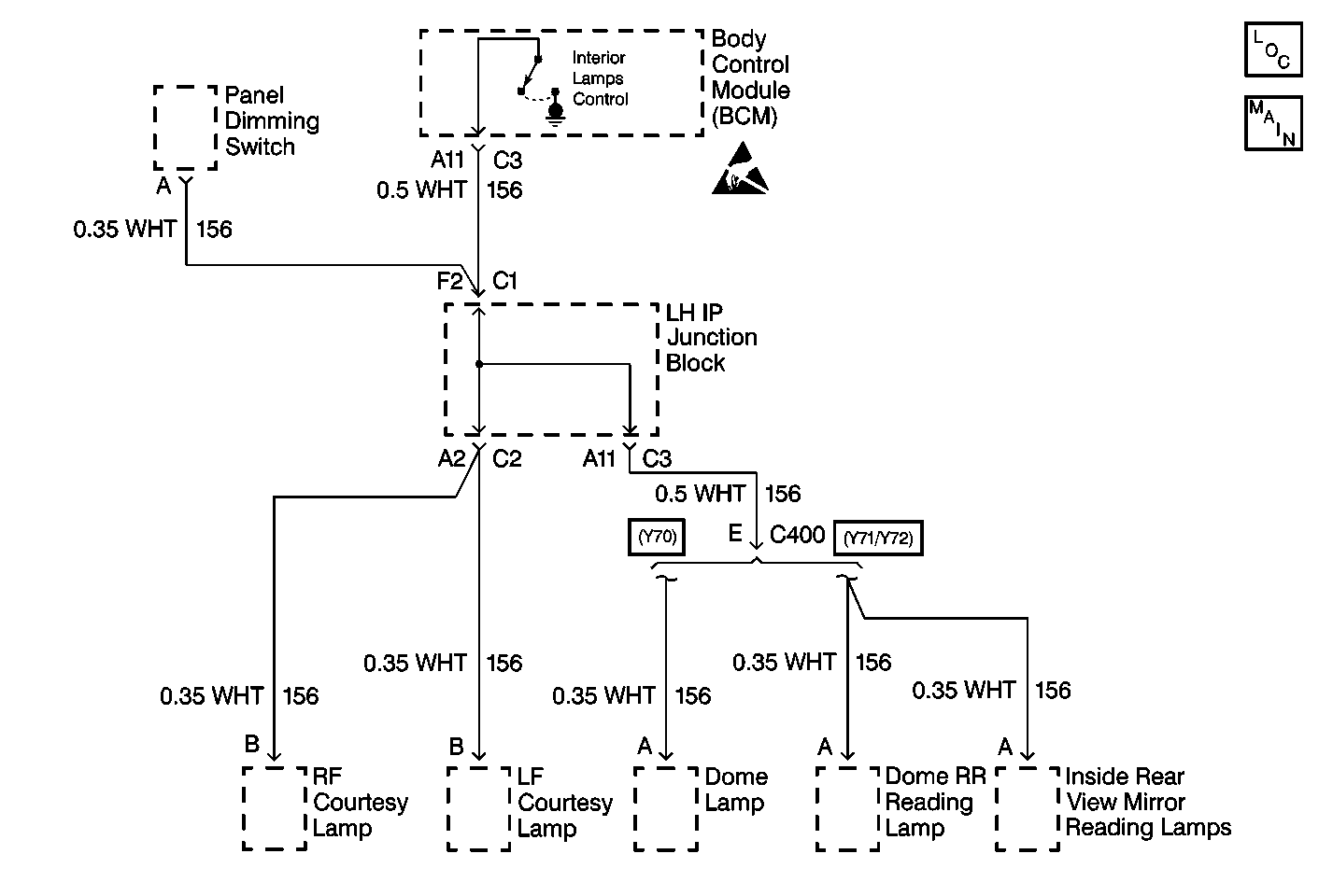
This step determines if a short to battery exists in CKT 156 or internal to the BCM.
-
This step determines if a short to battery exists in CKT 156, between the left IP wiring harness junction block and the BCM.
-
This step determines if a short to battery exists in CKT 156, between the following components:
-
This step determines if a short to battery exists in CKT 156, between the left IP wiring harness junction block and the dome lamp.
| • | The left IP wiring harness junction block |
| • | The left courtesy lamp |
| • | The right courtesy lamp |
Step | Action | Value(s) | Yes | No | ||
|---|---|---|---|---|---|---|
|
Important: A short to ground will cause an open fuse(s). Before performing this diagnostic procedure, inspect the fuse(s) for an open. | ||||||
1 | Was the Body Control Module (BCM) diagnostic system check performed? | -- | Go to Step 2 | Go to the Body Control Module System Check | ||
Is the measured voltage at the specified value? | 0V | Go to Step 10 | Go to Step 3 | |||
Is the measured voltage at the specified value? | 0V | Go to Step 5 | Go to Step 4 | |||
4 | Repair the short to B+ in CKT 156 between the BCM connector C3 terminal A11 and the left IP wiring harness junction block connector C1 terminal F2. Refer to Wiring Repairs in Wiring Systems. Is the circuit repair complete? | -- | Go to Step 11 | -- | ||
Use the J 39200 DMM in order to measure the voltage in CKT 156 between the left IP wiring harness junction block harness connector C2 terminal A2 and ground. Is the measured voltage at the specified value? | 0V | Go to Step 7 | Go to Step 6 | |||
6 | Repair the short to B+ condition in CKT 156 between the left IP wiring harness junction block connector C2 terminal A2 and the left courtesy lamp terminal B and the right courtesy lamp terminal B. Refer to Wiring Repairs in Wiring Systems. Is the repair complete? | -- | Go to Step 11 | -- | ||
Use the J 39200 DMM in order to measure the voltage in CKT 156 between the left IP wiring harness junction block harness connector C3 terminal A11 and ground. Is the measured voltage at the specified value? | 0V | Go to Step 9 | Go to Step 8 | |||
8 | Repair the short to B+ condition in CKT 156 between the left IP wiring harness junction block connector C3 terminal A11 and the dome lamp connector terminal A. Refer to Wiring Repairs in Wiring Systems. Is the repair complete? | -- | Go to Step 11 | -- | ||
9 | Replace the left IP wiring harness junction block. Is the repair complete? | -- | Go to Step 11 | -- | ||
10 | Replace the BCM. Refer to the following procedures:
Is the repair complete? | -- | Go to Step 11 | -- | ||
11 | Clear the DTCs from the memory. Are the DTCs cleared from the memory? | -- | Go to the Body Control Module System Check | -- | ||
