Circuit Description
Modules connected to the class 2 serial data circuit monitor for serial data communications during normal vehicle operation. Operating information and commands are exchanged among the modules. When a module receives a message for a critical operating parameter, the module records the ID number of the module which sent the message for State of Health monitoring (Node Alive messages). A critcal operating parameter is one which, when not received, requires that the module use a default value for that parameter. Once an ID number is learned by a module, it will monitor for that modules's "Node Alive" message. Each module on the class 2 serial data circuit which is powered and performing functions that require detection of a communications malfunction is required to send a "Node Alive" message every two seconds. When no message is detected from the body control module (BCM) for five seconds, DTC U1064 is set.
Conditions for Setting the DTC
The ignition is turned to the ON position, and a module on the class 2 serial data circuit does not receive the BCM ID for 5 seconds.
Conditions for Clearing the DTC
| • | A current DTC will clear when a "Node Alive" message from the BCM is detected on the class 2 serial data circuit or at the end of the current ignition cycle. |
| • | A history DTC can be cleared with the scan tool. |
Diagnostic Aids
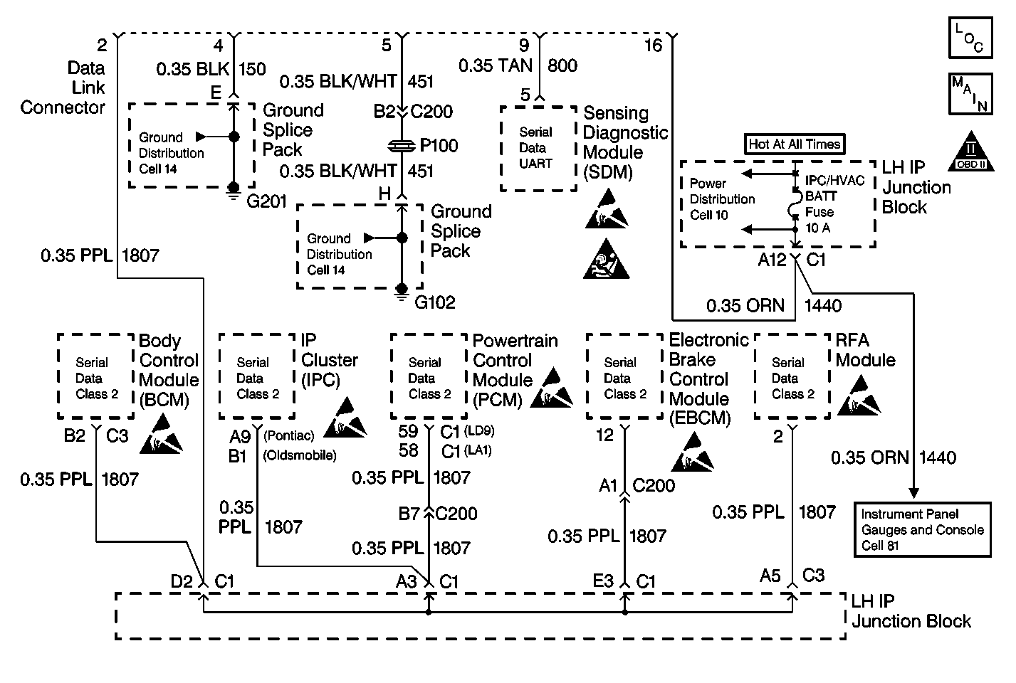
When multiple Loss of Communication DTCs are set concurrently, the cause is likely to be two opens in the class 2 serial data circuit. Use the Data Link Schematic in order to determine the location of the opens.
Step | Action | Value(s) | Yes | No |
|---|---|---|---|---|
|
Important: A short to ground will cause an open fuse(s). Before performing this diagnostic procedure, inspect the fuse(s) for an open. | ||||
1 | Test the battery positive voltage circuits to the BCM for an open or a short to ground. Did you find and correct the condition? | -- | Go to Step 5 | Go to Step 2 |
2 |
Did you find and correct the condition? | -- | Go to Step 5 | Go to Step 4 |
3 | Inspect for poor connections at the battery positive voltage circuits, the ground circuits and the class 2 serial data circuit to the BCM. Did you find and correct the condition? | -- | Go to Step 5 | Go to Step 4 |
4 | Replace the BCM. Refer to Body Control Module Replacement in Body Control Systems. Is the repair complete? | -- | Go to Step 5 | -- |
5 | Select the DISPLAY DTCs function for the BCM. Does the scan tool display any DTCs which do not begin with "U"? | -- | Go to the applicable DTC table | Go to Step 6 |
6 |
Is the action complete? | -- | -- | |
