Removal Procedure
- Turn the ignition switch to the OFF position.
- Disconnect the negative battery cable. Refer to Battery Negative Cable Disconnection and Connection.
- Drain the cooling system. Refer to Cooling System Draining and Filling.
- Remove the intake manifold sight shield or the fuel injector sight shield. Refer to Intake Manifold Sight Shield Replacement (LC3) or Fuel Injector Sight Shield Replacement (LH2).
- If equipped with RPO LH2, remove the air cleaner inlet duct. Refer to Air Cleaner Inlet Duct Replacement.
- Disconnect the upper radiator hose. Refer to Radiator Inlet Hose Replacement.
- Disconnect the radiator surge tank inlet hose. Refer to Radiator Surge Tank Inlet Hose/Pipe Replacement.
- Remove the drive belt tensioner. Refer to Supercharger Belt Tensioner Replacement (LC3) or Drive Belt Tensioner Replacement (LH2).
- Clean the area surrounding the electronic brake control module (EBCM) and the brake pressure modulator valve (BPMV) of and dirt and debris.
- Disconnect the EBCM electrical connector.
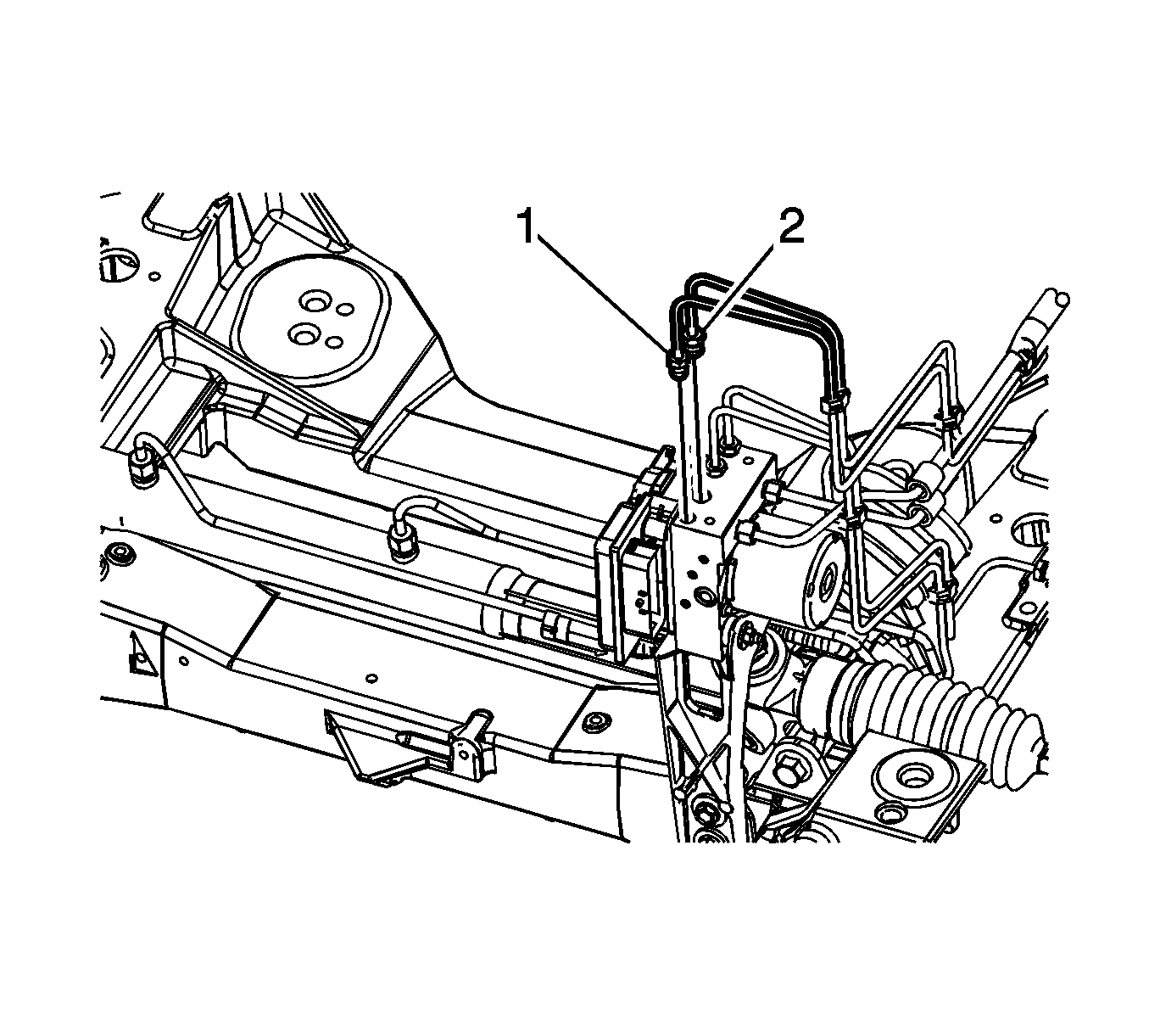
- Disconnect the left rear brake pipe fitting (1).
- Disconnect the right rear brake pipe fitting (2).
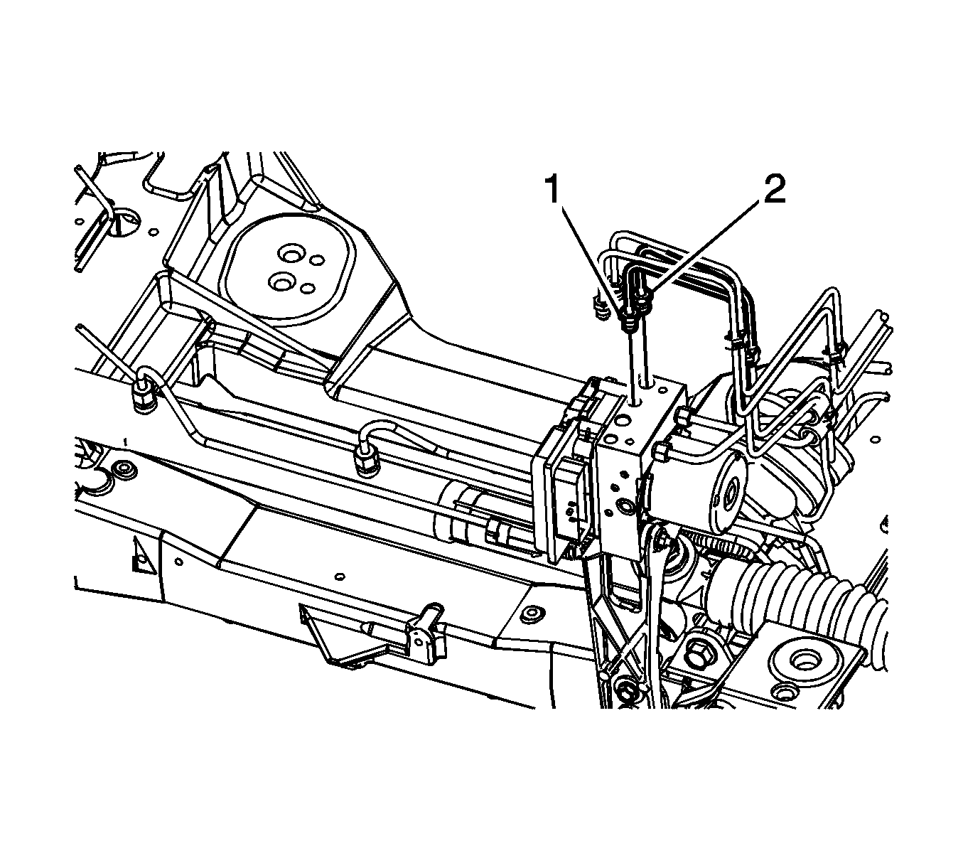
- Disconnect the right front brake pipe fitting (1).
- Disconnect the left front brake pipe fitting (2).
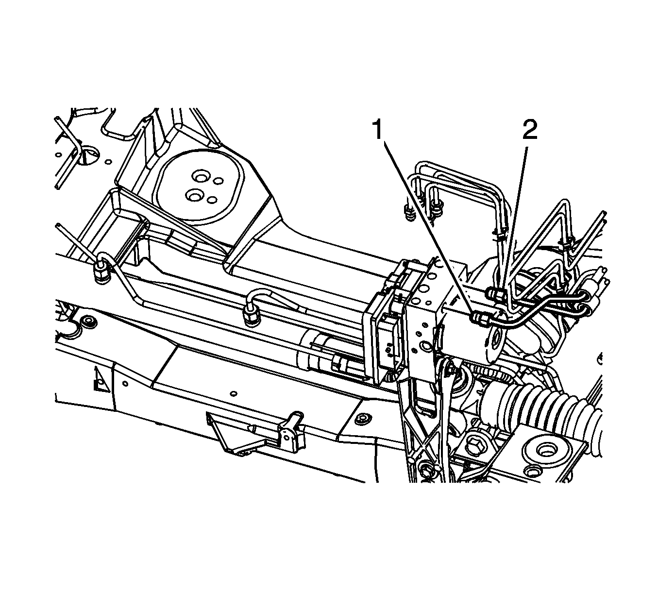
- Disconnect the master cylinder secondary brake pipe fitting (1).
- Disconnect the master cylinder primary brake pipe fitting (2).
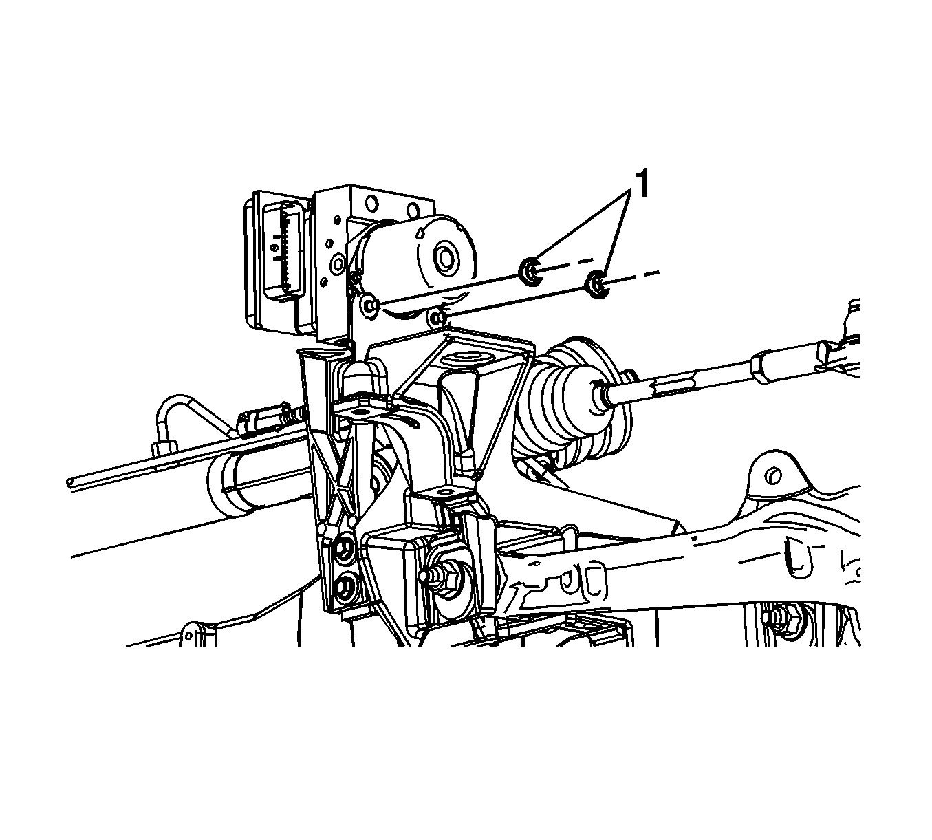
- Remove the BPMV nuts (1).
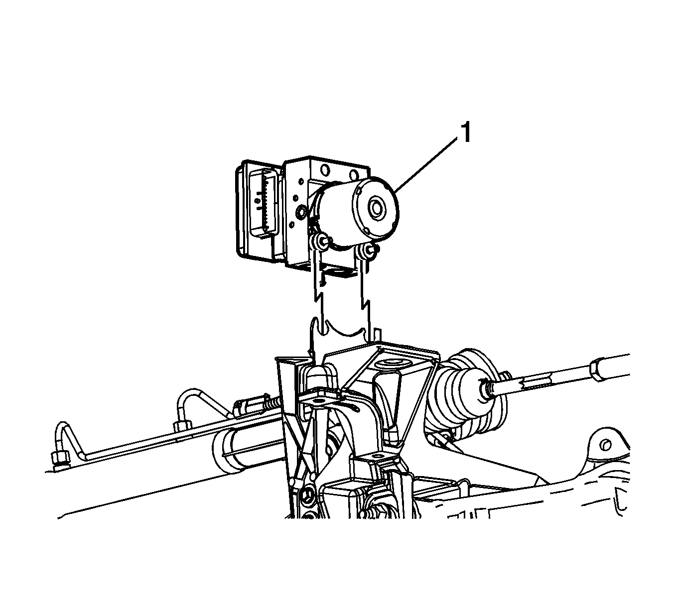
- Remove the EBCM/BPMV module assembly (1) from the bracket.
- Remove the BPMV insulators (1).
- Remove the EBCM bolts (1).
- Carefully remove the EBCM (1) from the BPMV.
- Clean the mating surfaces of the EBCM and the BPMV with denatured alcohol and allow to dry.
Caution: To prevent equipment damage, never connect or disconnect the wiring harness connection from the EBCM with the ignition switch in the ON position.
Position the hose aside.
Position the hose aside.
Cap the brake pipe fitting and plug the BPMV outlet port to prevent brake fluid leaks and contamination.
Cap the brake pipe fitting and plug the BPMV outlet port to prevent brake fluid leaks and contamination.
Cap the brake pipe fitting and plug the BPMV outlet port to prevent brake fluid leaks and contamination.
Do not force the components apart.
Cap the brake pipe fitting and plug the BPMV outlet port to prevent brake fluid leaks and contamination.
Cap the brake pipe fitting and plug the BPMV inlet port to prevent brake fluid leaks and contamination.
Cap the brake pipe fitting and plug the BPMV inlet port to prevent brake fluid leaks and contamination.
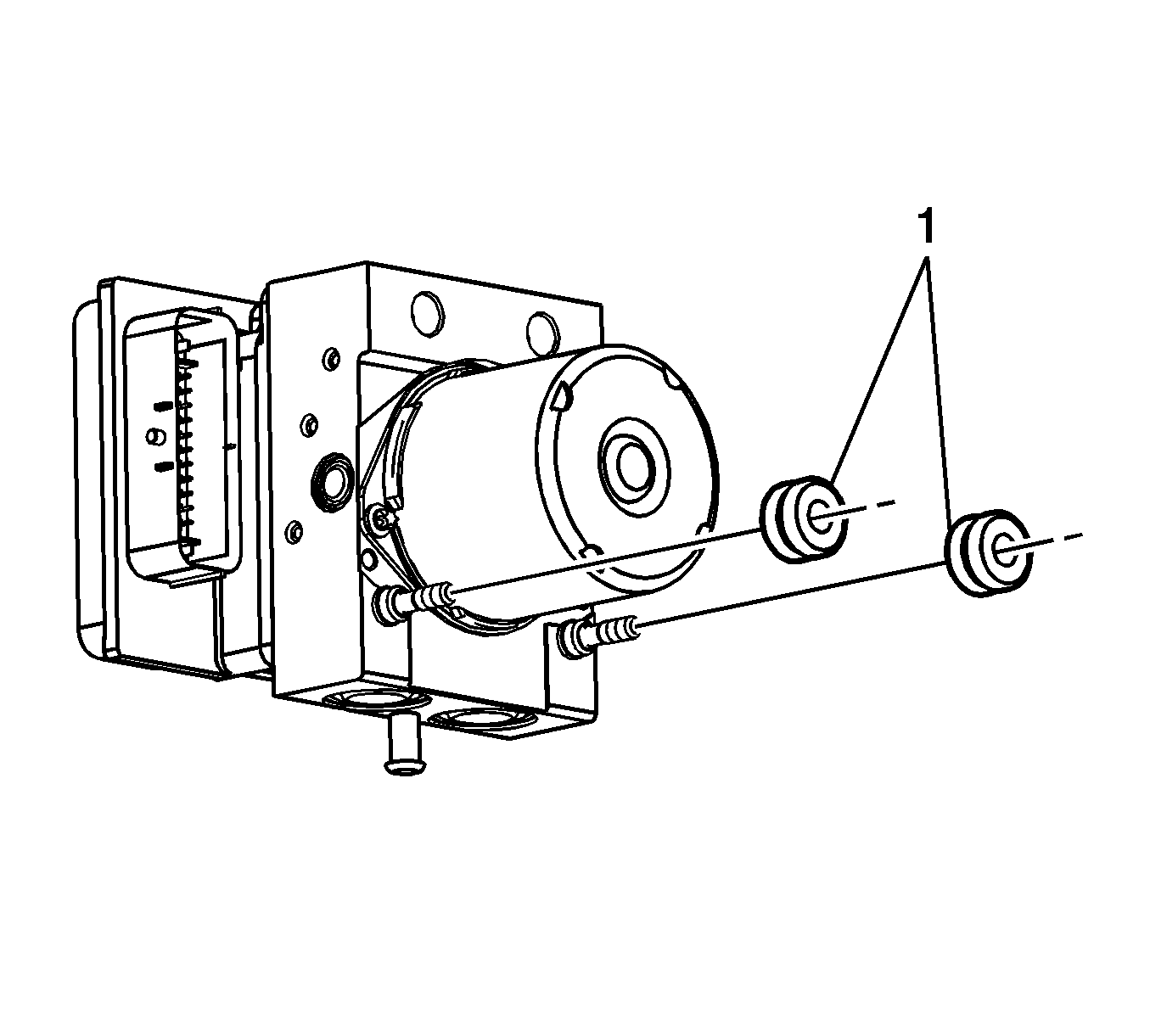
Inspect the insulators for damage and replace, if necessary.
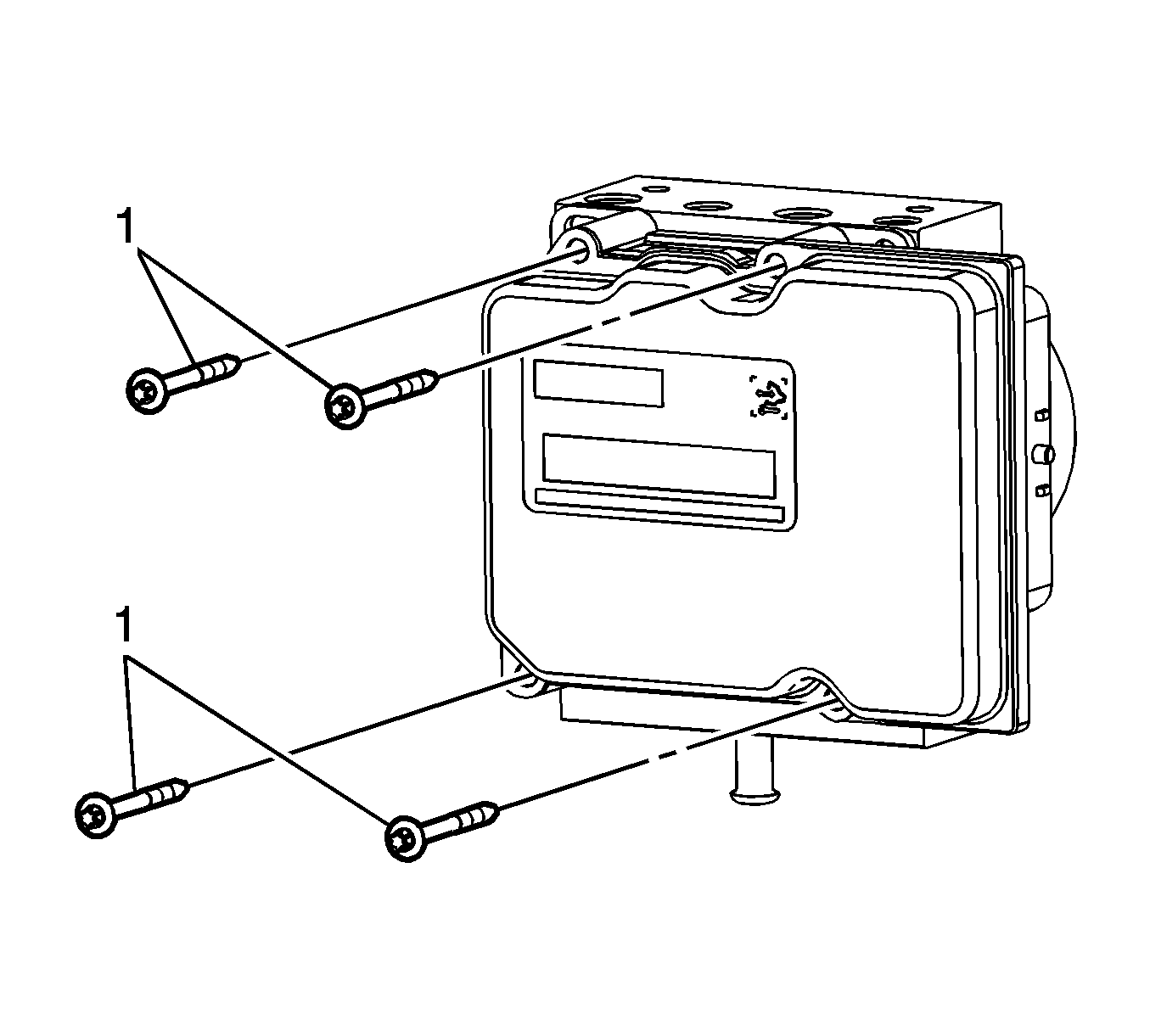
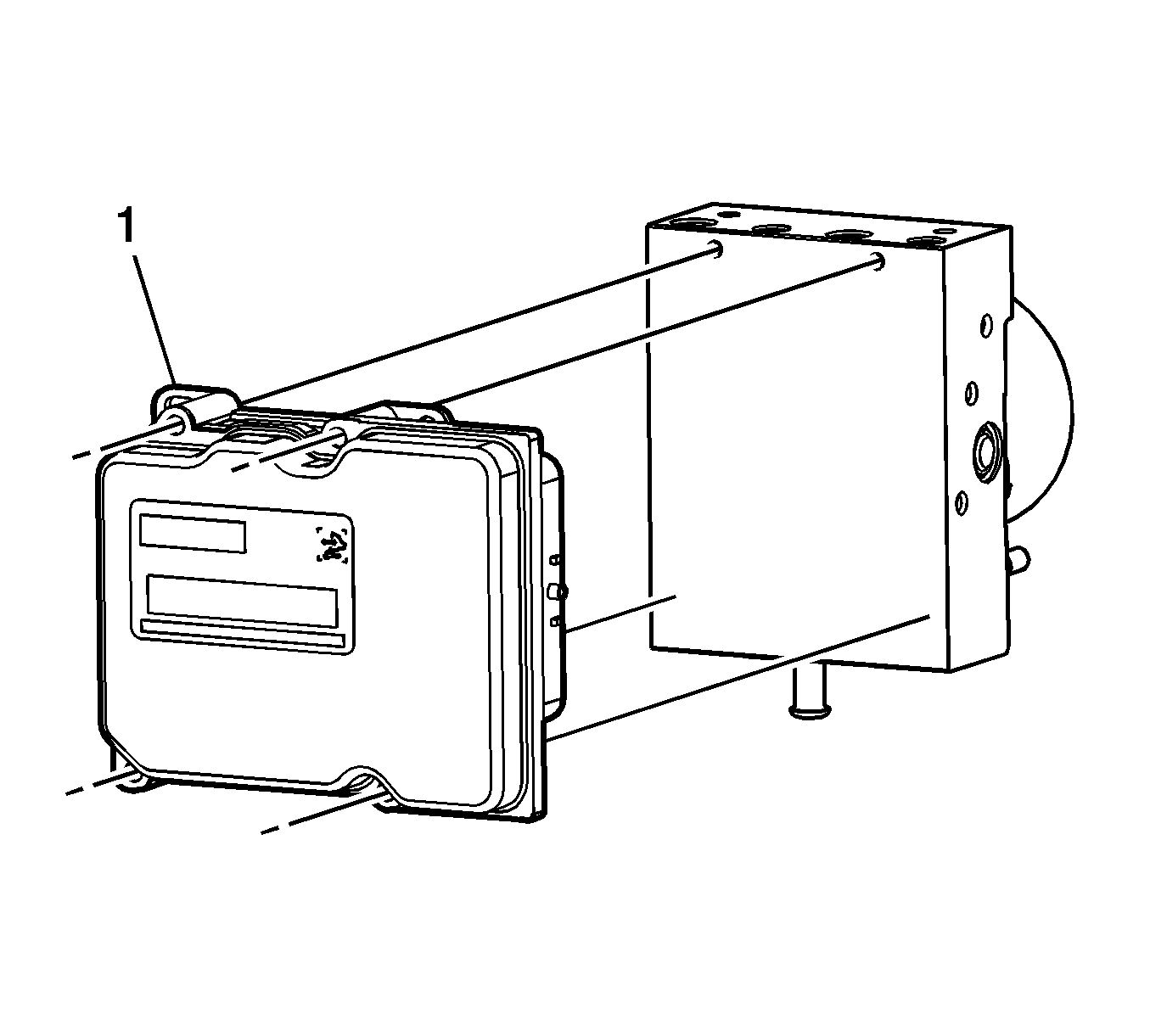
Note: Do not attempt to pry or lever the EBCM from the BPMV.
Do not force the components apart.
Installation Procedure
- Carefully install the EBCM (1) to the BPMV.
- Install the EBCM bolts (1) and tighten to 3 N·m (27 lb in).
- Install the BPMV insulators (1).
- Install the EBCM/BPMV module assembly to the bracket.
- Install the BPMV nuts (1) and tighten to 12 N·m (106 lb in).
- Connect the master cylinder secondary brake pipe fitting (1) and tighten to 18 N·m (13 lb ft).
- Connect the master cylinder primary brake pipe fitting (2) and tighten to 18 N·m (13 lb ft).
- Connect the right front brake pipe fitting (1) and tighten to 18 N·m (13 lb ft).
- Connect the left front brake pipe fitting (2) and tighten to 18 N·m (13 lb ft).
- Connect the left rear brake pipe fitting (1) and tighten to 18 N·m (13 lb ft).
- Connect the right rear brake pipe fitting (2) and tighten to 18 N·m (13 lb ft).
- Install the drive belt tensioner. Refer to Supercharger Belt Tensioner Replacement (LC3) or Drive Belt Tensioner Replacement (LH2).
- Install the intake manifold sight shield or the fuel injector sight shield. Refer to Intake Manifold Sight Shield Replacement (LC3) or Fuel Injector Sight Shield Replacement (LH2).
- Connect the radiator surge tank inlet hose. Refer to Radiator Surge Tank Inlet Hose/Pipe Replacement.
- If equipped with RPO LH2, install the air cleaner inlet duct. Refer to Air Cleaner Inlet Duct Replacement.
- Connect the upper radiator hose. Refer to Radiator Inlet Hose Replacement.
- Fill the cooling system. Refer to Cooling System Draining and Filling.
- Connect the EBCM electrical connector.
- Connect the negative battery cable. Refer to Battery Negative Cable Disconnection and Connection.
- If installing a new EBCM, program the EBCM. Refer to Service Programming System (SPS).
- Perform the Antilock Brake System Automated Bleed Procedure.

Do not force the components together.
Caution: Refer to Fastener Caution in the Preface section.


