For 1990-2009 cars only
Removal Procedure
- Remove the intake manifold sight shield. Refer to Intake Manifold Sight Shield Replacement.
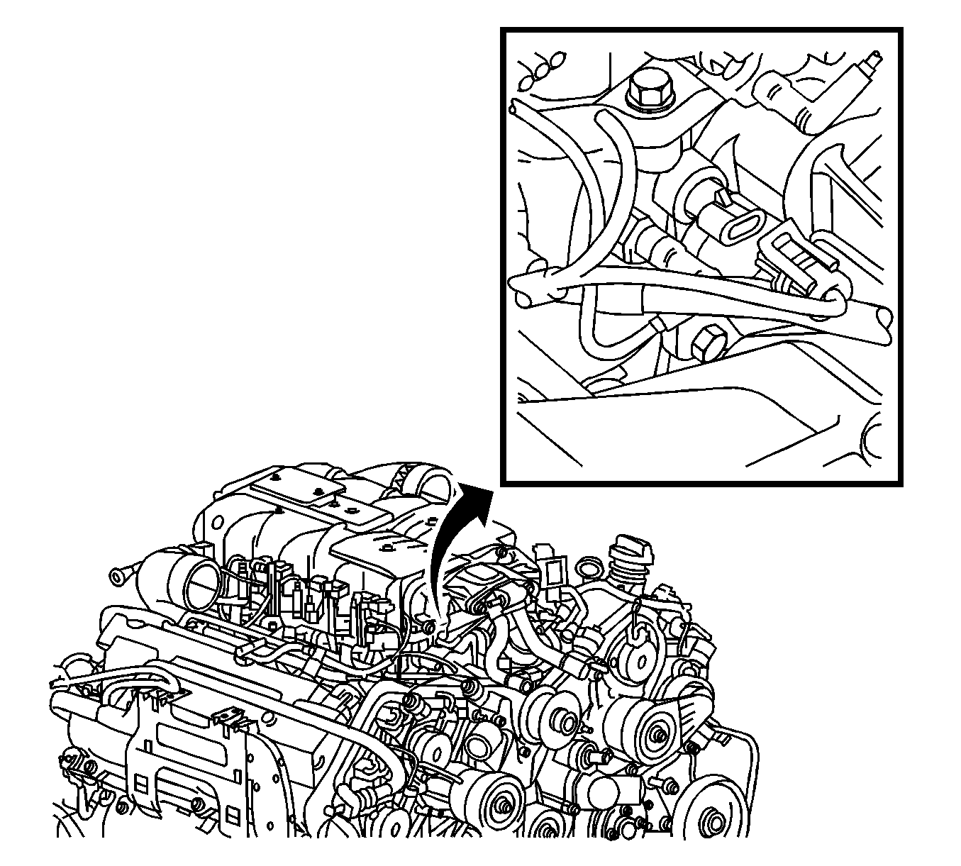
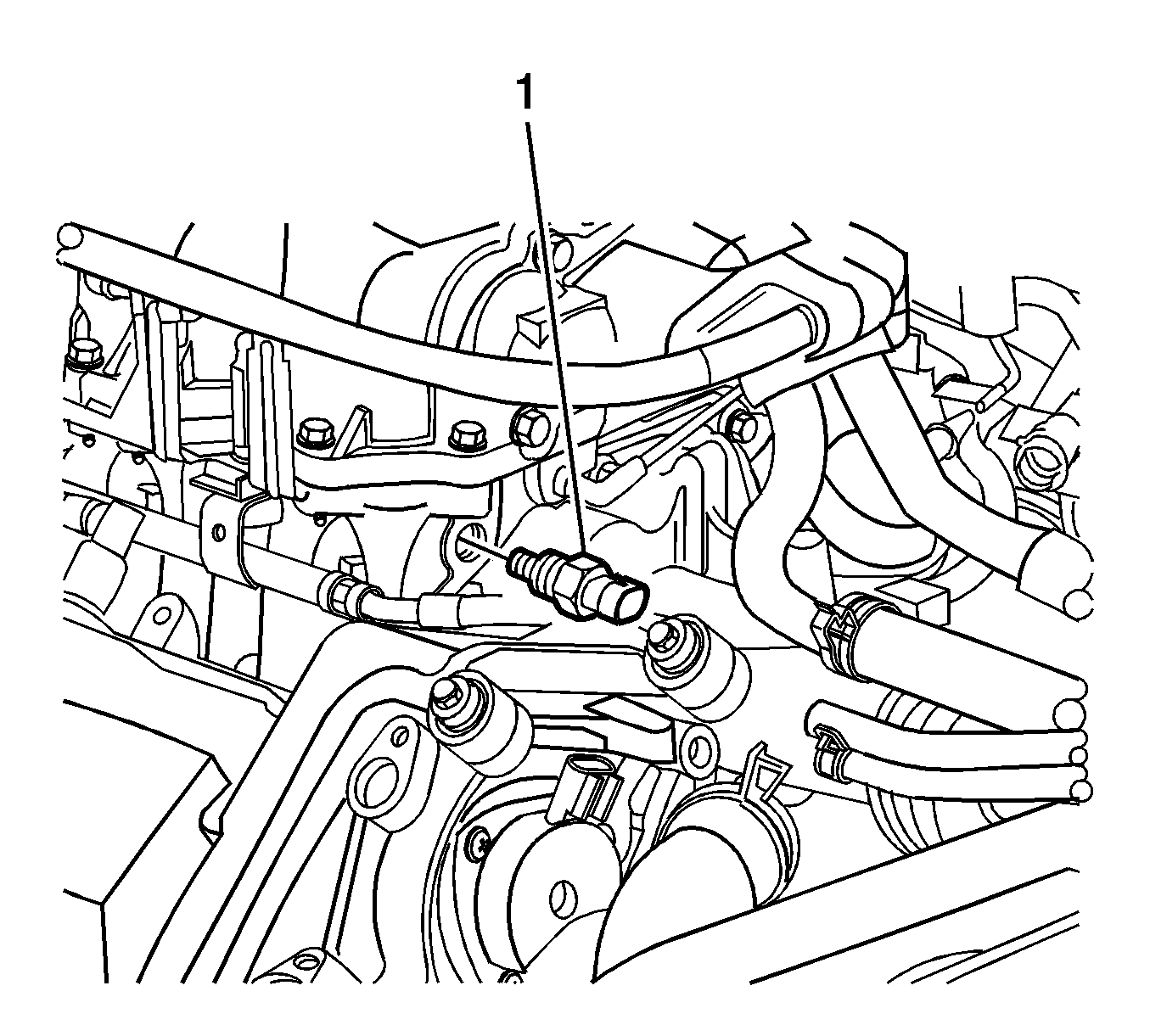
- Disconnect the intake air temperature (IAT) sensor 2 electrical connector.
- Remove the IAT sensor 2 (1).


Installation Procedure
- Coat the sensor threads with sealer. Refer to Adhesives, Fluids, Lubricants, and Sealers.
- Install the IAT sensor 2 (1) and tighten to 20 N·m (15 lb ft).
- Connect the IAT sensor 2 electrical connector.
- Install the intake manifold sight shield. Refer to Intake Manifold Sight Shield Replacement.

Caution: Replacement components must be the correct part number for the application. Components requiring the use of the thread locking compound, lubricants, corrosion inhibitors, or sealants are identified in the service procedure. Some replacement components may come with these coatings already applied. Do not use these coatings on components unless specified. These coatings can affect the final torque, which may affect the operation of the component. Use the correct torque specification when installing components in order to avoid damage.
Caution: Refer to Fastener Caution in the Preface section.

