For 1990-2009 cars only
Tools Required
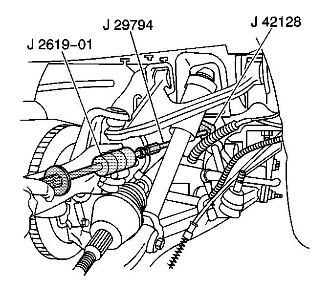
| • | J 2619-O1 Slide Hammer |
| • | J 29794 Extension |
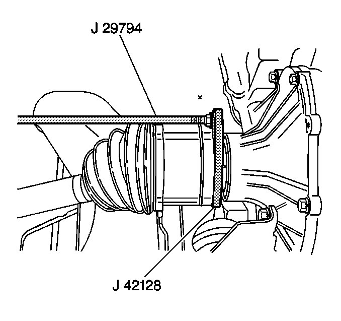
| • | J 42128 Axle Shaft Remover |
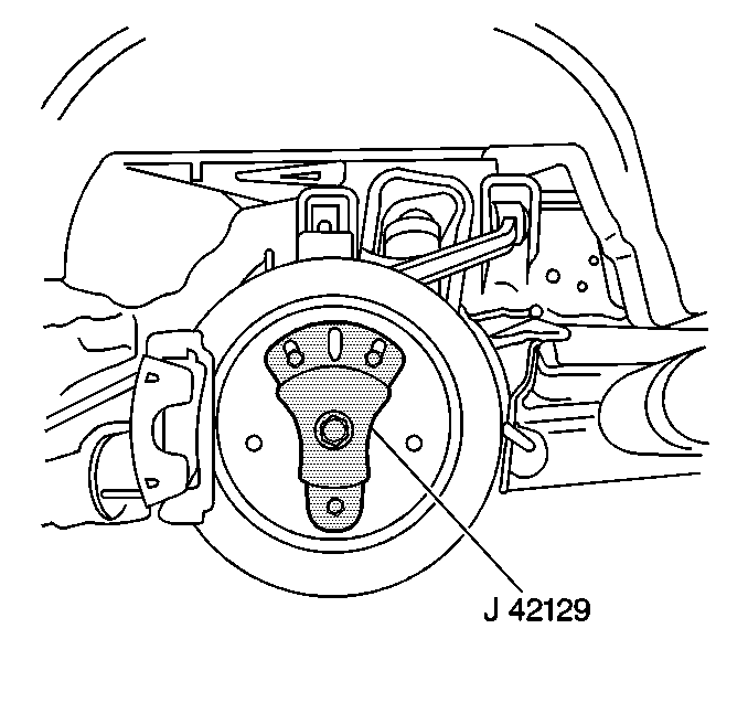
| • | J 42129 Rear Hub Spindle Remover |
Removal Procedure
- Raise and suitably support the vehicle. Refer to Lifting and Jacking the Vehicle .
- Remove the tire and wheel assembly. Refer to Tire and Wheel Removal and Installation .
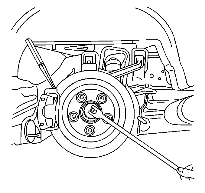
- Insert a drift or punch into the brake rotor cooling fins and against the brake caliper to prevent the wheel hub and bearing from turning.
- Remove the spindle nut retaining the rear wheel drive shaft to the hub.
- Remove the drift or punch.
- Separate the outer tie rod end from the knuckle and reposition the tie rod toward the rear of the vehicle. Refer to Tie Rod Replacement .
- Disconnect the wheel speed sensor electrical connector.
- Remove the parking brake cable from the bracket.
- Disconnect the parking brake cable from the parking brake lever and reposition the cable toward the rear.
- Remove the parking brake cable from the bracket and reposition toward the rear.
- Install J 42129 onto the wheel hub and secure with wheel nuts.
- Begin to disengage the drive shaft from the wheel hub and bearing.
- Remove the lower shock nut and bolt. Refer to Shock Absorber Replacement .
- Separate the upper ball joint from the suspension knuckle. Refer to Rear Axle Upper Control Arm Replacement .
- Disengage the drive shaft completely from the wheel hub and bearing.
- Support the drive shaft.
- Support the suspension knuckle and upper control arm and reposition the knuckle toward the front of the vehicle.
- Assemble the J 42128 , J 29794 , and J 2619-O1 .
- Install the J 42128 evenly onto the rear beveled surface of the drive shaft inner joint housing.
- Disengage the drive shaft from the rear axle differential using the J 42128 , J 29794 , and J 2619-O1 , then remove the tool assembly.
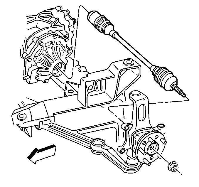
- Remove the drive shaft from the vehicle.
- Remove J 42129 from the wheel hub.
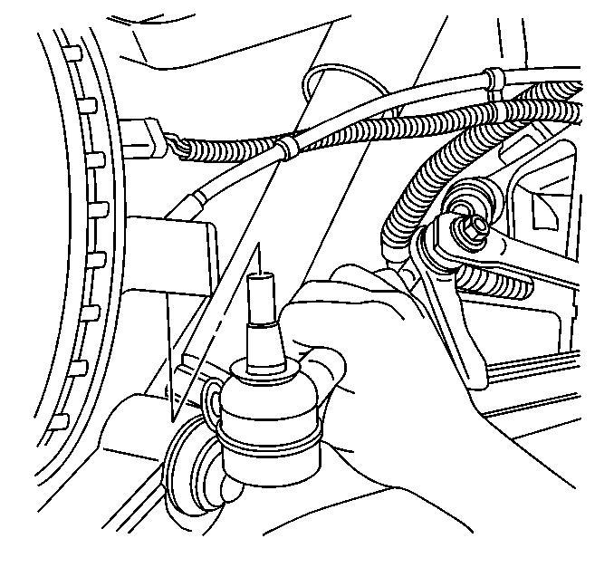
Important: Do not loosen the outer tie rod jam nut.
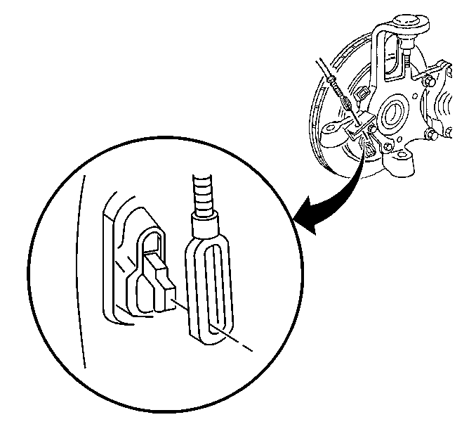
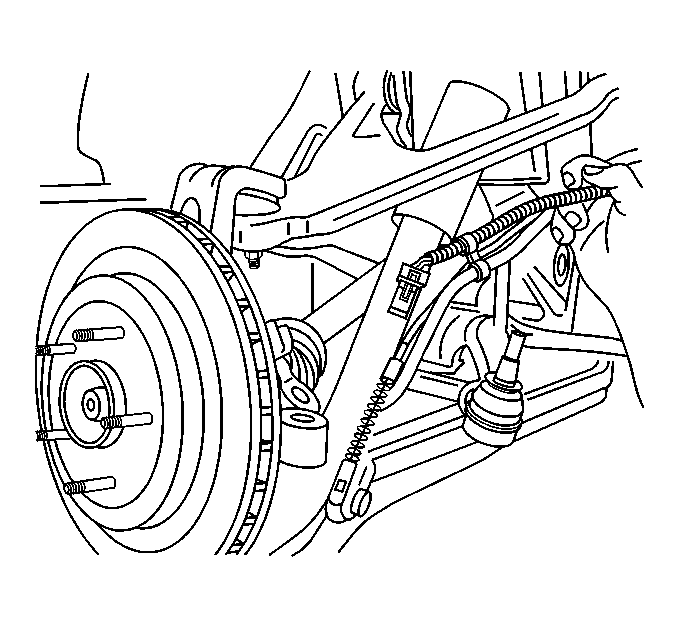
Important: Be sure to support the drive shaft until it is removed.
Installation Procedure
- Clean and inspect the journal on the axle shaft prior to installation.
- Position the drive shaft to the rear axle differential output shaft.
- Carefully align and guide the drive shaft onto the differential output shaft.
- Engage the drive shaft fully onto the differential output shaft using light force.
- Check to be certain that the drive shaft is fully seated on the differential output shaft.
- Align and carefully guide the drive shaft into the wheel hub and bearing .
- Connect the upper ball joint to the suspension knuckle. Refer to Rear Axle Upper Control Arm Replacement .
- Install the lower shock bolt and nut. Refer to Shock Absorber Replacement .
- Connect the parking brake cable to the parking brake lever.
- Install the parking brake cable into the bracket.
- Connect the wheel speed sensor electrical connector.
- Connect the outer tie rod end to the suspension knuckle. Refer to Tie Rod Replacement .
- Insert a drift or punch into the brake rotor cooling fins and against the caliper to prevent the wheel hub and bearing from turning.
- Begin to install the drive shaft retaining nut onto the drive shaft by hand.
- Slowly tighten the nut to draw the drive shaft to the wheel hub and bearing.
- Remove the drift or punch.
- Install the tire and wheel assembly. Refer to Tire and Wheel Removal and Installation .
- Lower the vehicle.

Important: Be sure to support the drive shaft until it is completely installed.
Important: Use care not to damage the rear axle differential output shaft seal.


Tighten
Tighten the drive axle spindle nut to 205 N·m (151 lb ft).
