For 1990-2009 cars only
Removal Procedure
- Open the trunk.
- Disconnect the electronic suspension control module connectors from the module. Refer to Electronic Suspension Control Module Replacement.
- Close the trunk.
- Disconnect the battery negative cable. Refer to Battery Negative Cable Disconnection and Connection.
- Recover the air conditioning (A/C) refrigerant. Refer to Refrigerant Recovery and Recharging.
- Remove the fuel injector sight shield. Refer to Fuel Injector Sight Shield Replacement.
- Relieve the fuel system pressure. Refer to Fuel Pressure Relief.
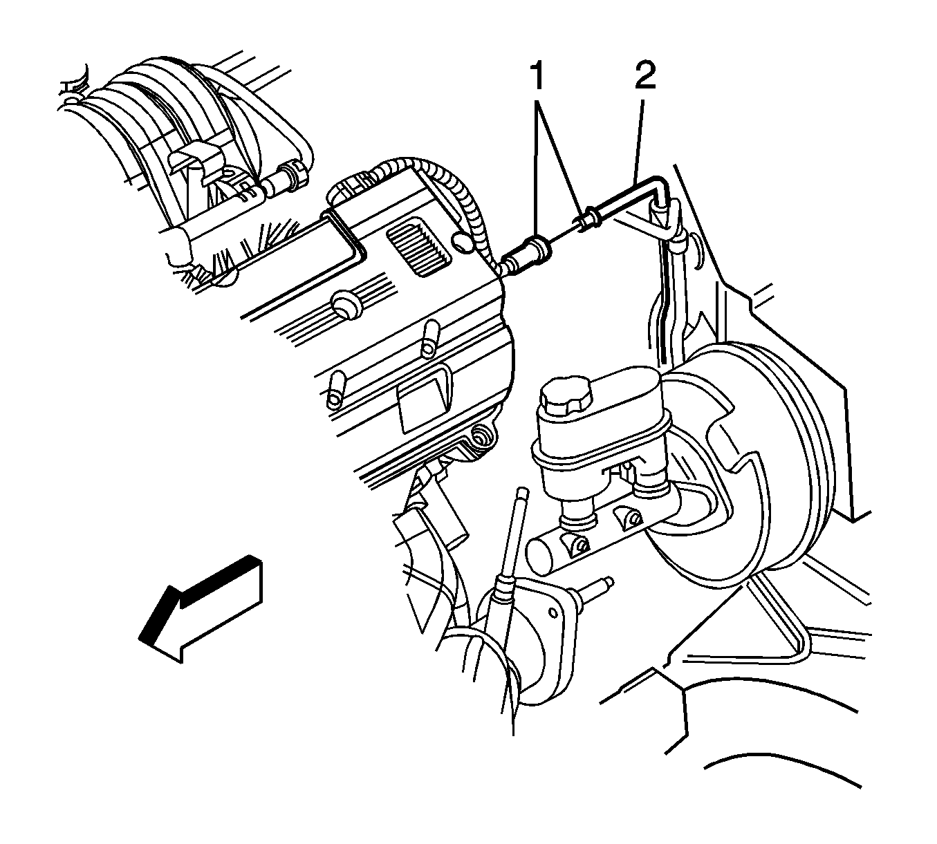
- Disconnect the evaporative emission (EVAP) canister purge pipe (1) from the chassis purge pipe (2).
- Cap the open pipes in order to prevent possible contamination.
- Disconnect the fuel inlet quick-connect fitting at the fuel line and secure. Refer to Metal Collar Quick Connect Fitting Service.
- Remove the air cleaner assembly. Refer to Air Cleaner Assembly Replacement.
- Remove the radiator. Refer to Radiator Replacement.
- Remove the surge tank. Refer to Radiator Surge Tank Replacement.
- Remove the air conditioning condenser. Refer to Air Conditioning Condenser Replacement.
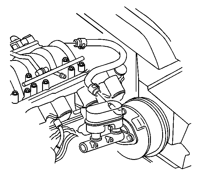
- Disconnect the vacuum brake booster hose from the brake booster.
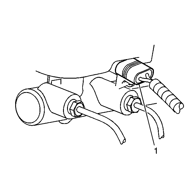
- Disconnect the electrical connector (1) from the brake fluid level sensor.
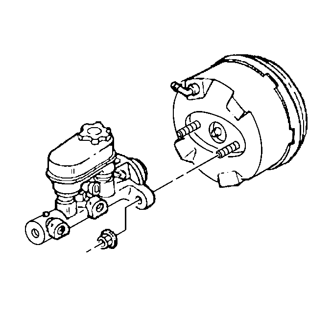
- Remove the brake master cylinder nuts from the brake booster studs.
- Pull the master cylinder forward out of contact with the brake booster studs.
- Secure the master cylinder to the engine.
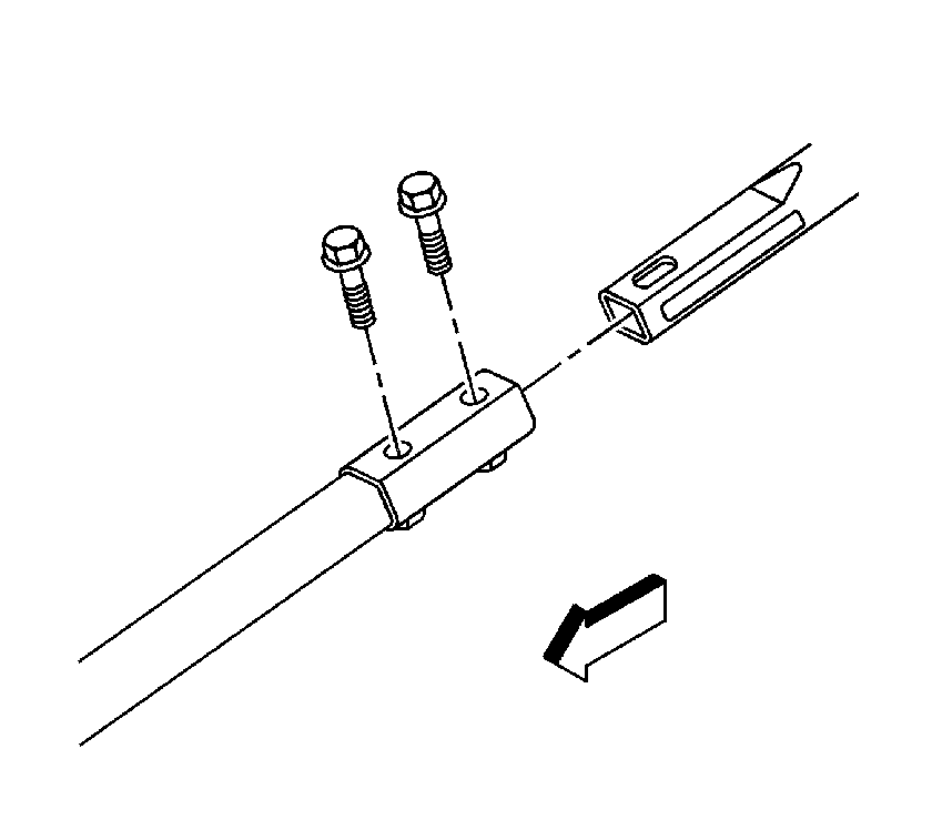
- Remove the bolts from the intermediate steering shaft.
- Disconnect the steering shaft from the steering gear.
- Tie-wrap the steering shaft to the engine.
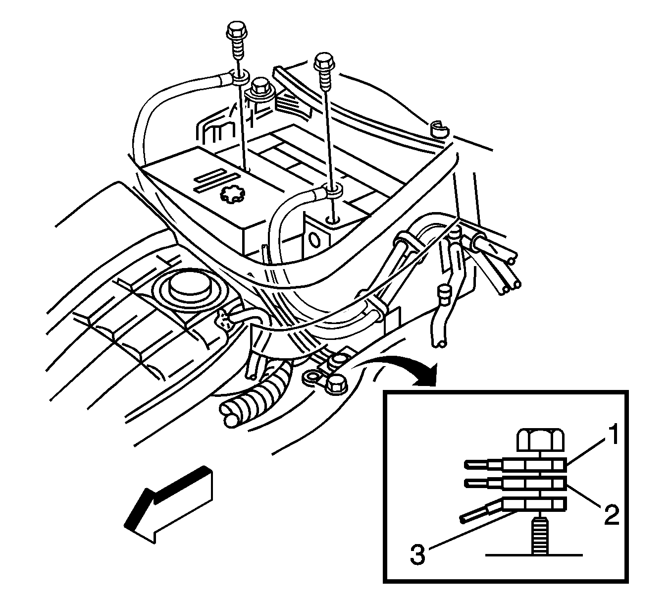
- Remove the battery. Refer to Battery Replacement.
- Remove the battery tray. Refer to Battery Tray Replacement.
- Remove the ground strap nut and terminal from the stud on the frame.
- Disconnect the A/C electrical connector from the pressure sensor.
- Remove the UHJB from the wheelhouse.
- Disconnect the wiring harness connector from the UHJB.
- Secure the wiring harness to the engine.
- Raise and support the vehicle. Refer to Lifting and Jacking the Vehicle.
- Remove the front wheels and tires. Refer to Tire and Wheel Removal and Installation.
- Remove the right front wheelhouse panel (access to the engine control module (ECM)/transmission control module (TCM) electrical connectors). Refer to Front Wheelhouse Rear Liner Replacement.
- Disconnect and secure the following wiring harness electrical connectors to the top of engine:
- Disconnect A/C lines from front of dash connections. Refer to Air Conditioning Compressor Hose Replacement.
- Disconnect heater hoses from heater pipes. Refer to Heater Pipes Replacement.
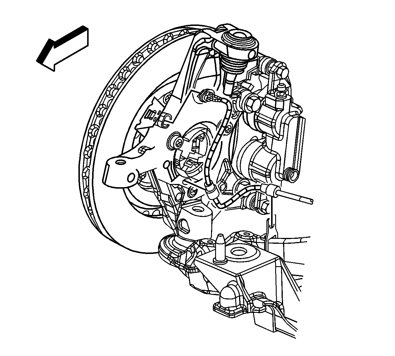
- Disconnect the front wheel speed sensor electrical connectors.
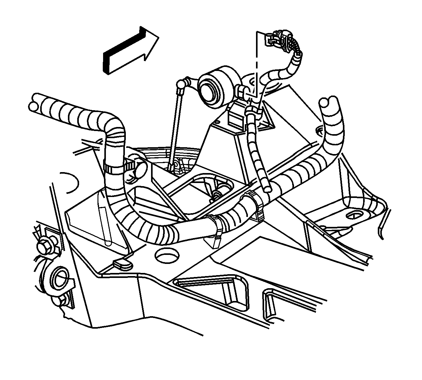
- Disconnect the road sensing suspension position sensor links from the front lower control arms.
- Support the lower control arm with a straight jack.
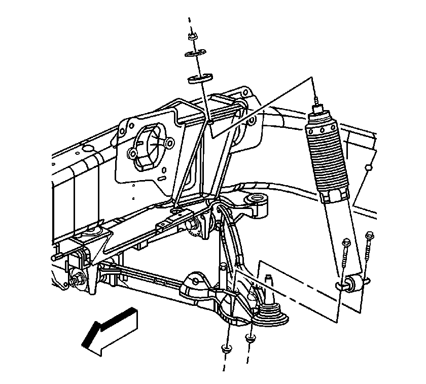
- Remove the shock absorber lower mounting bolts.
- Disconnect the upper ball joint from the suspension knuckle. Refer to Steering Knuckle Replacement.
- Remove the straight jack from the control arm.
- Repeat steps-through-for the other side of the vehicle.
- Remove the rear tire and wheel assemblies. Refer to Tire and Wheel Removal and Installation.
- Disconnect the rear park brake cables from the actuators. Refer to Parking Brake Rear Cable Replacement.
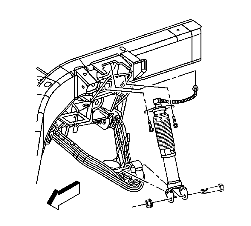
- Disconnect the rear wheel speed sensor electrical connectors.
- Disconnect the road sensing suspension position sensor links from the rear lower control arms.
- Support the lower control arm with a straight jack.
- Remove the rear shock absorber lower mounting bolt.
- Disconnect the upper ball joint from the suspension knuckle. Refer to Knuckle Replacement.
- Remove the straight jack from the control arm.
- Repeat steps-through-for the other side of the vehicle.
- Remove the RH muffler assembly. Refer to Exhaust Muffler Replacement - Right Side.
- Remove the LH muffler assembly. Refer to Exhaust Muffler Replacement - Left Side.
- Remove the exhaust intermediate pipe. Refer to Intermediate Pipe Replacement.
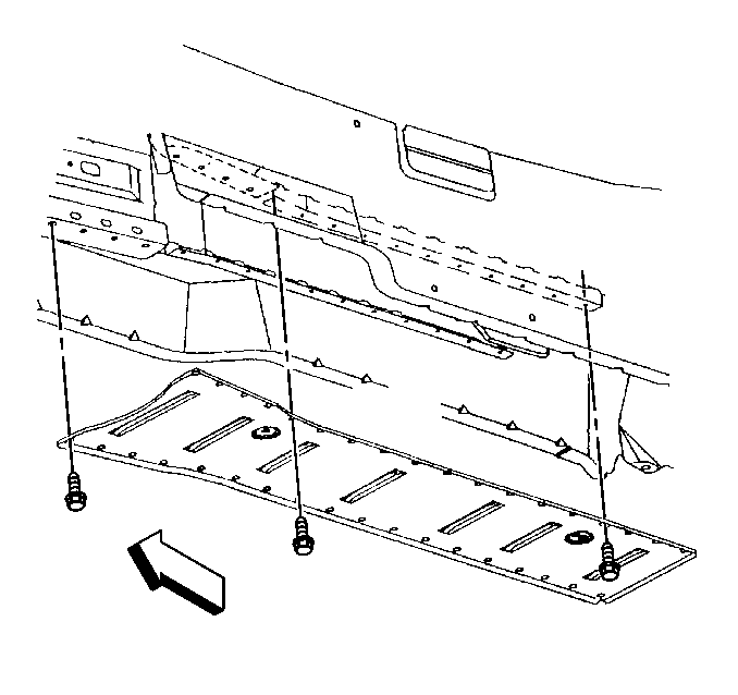
- Remove the bolts from the driveline tunnel closeout panel.
- Remove the driveline tunnel closeout panel.
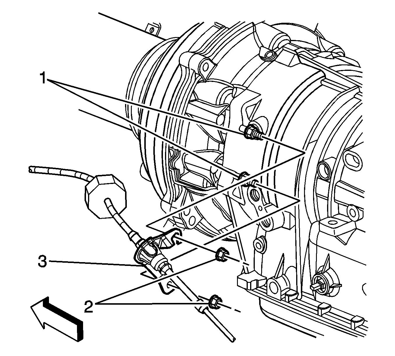
- Remove the nuts retaining the transmission shift cable bracket to the transmission.
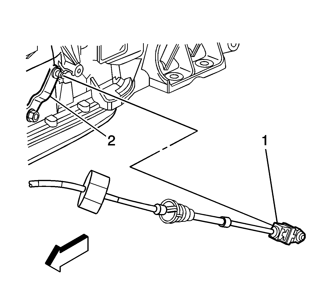
- Disconnect the transmission shift control cable from the transmission shift lever. Unsnap to release the cable.
- Reposition the transmission shift cable and bracket.
- Disconnect the wiring harness and ground from the rear crossmember.
- Remove the rear brake intermediate pipes from the clips and place the pipes near the driveline support assembly.
- Disconnect the wiring harness connectors from the bank 1 and bank 2 sensor 1 oxygen sensors. Refer to Heated Oxygen Sensor Replacement - Bank 1 Sensor 1 and Heated Oxygen Sensor Replacement - Bank 2 Sensor 1.
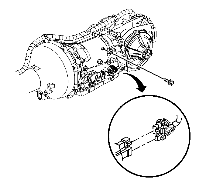
- Disconnect the park/neutral position switch electrical connectors.
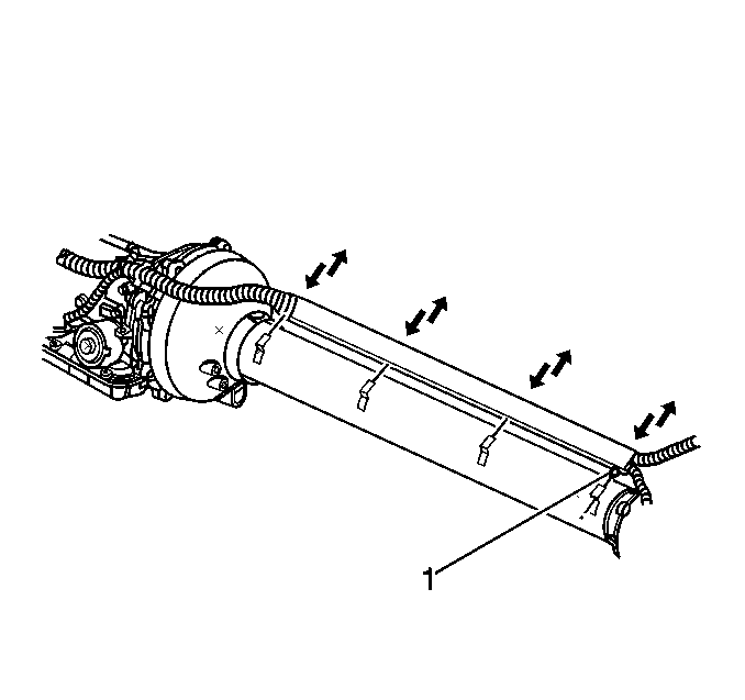
- Remove the bolt retaining the transmission wiring harness to the transmission case.
- Release the wiring harness from the harness retainer along the top of the transmission.
- Position the powertrain table under the front cradle.
- Position the powertrain table under the rear cradle.
- With the aid of an assistant, slowly lower the vehicle onto the powertrain tables.
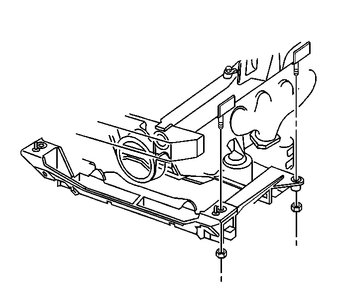
- Using HAND TOOLS ONLY, remove the front and rear crossmember nuts. Refer to Front Suspension Crossmember Replacement.
- Carefully raise the vehicle to clear the supported powertrain assembly.
Important: Cap the hoses and inlets when separating the cooling system components. This prevents dirt and other contaminants from entering the cooling system.
Caution: Refer to Brake Fluid Irritant Caution in the Preface section.
Important: The brake hydraulic system does not need to be opened.
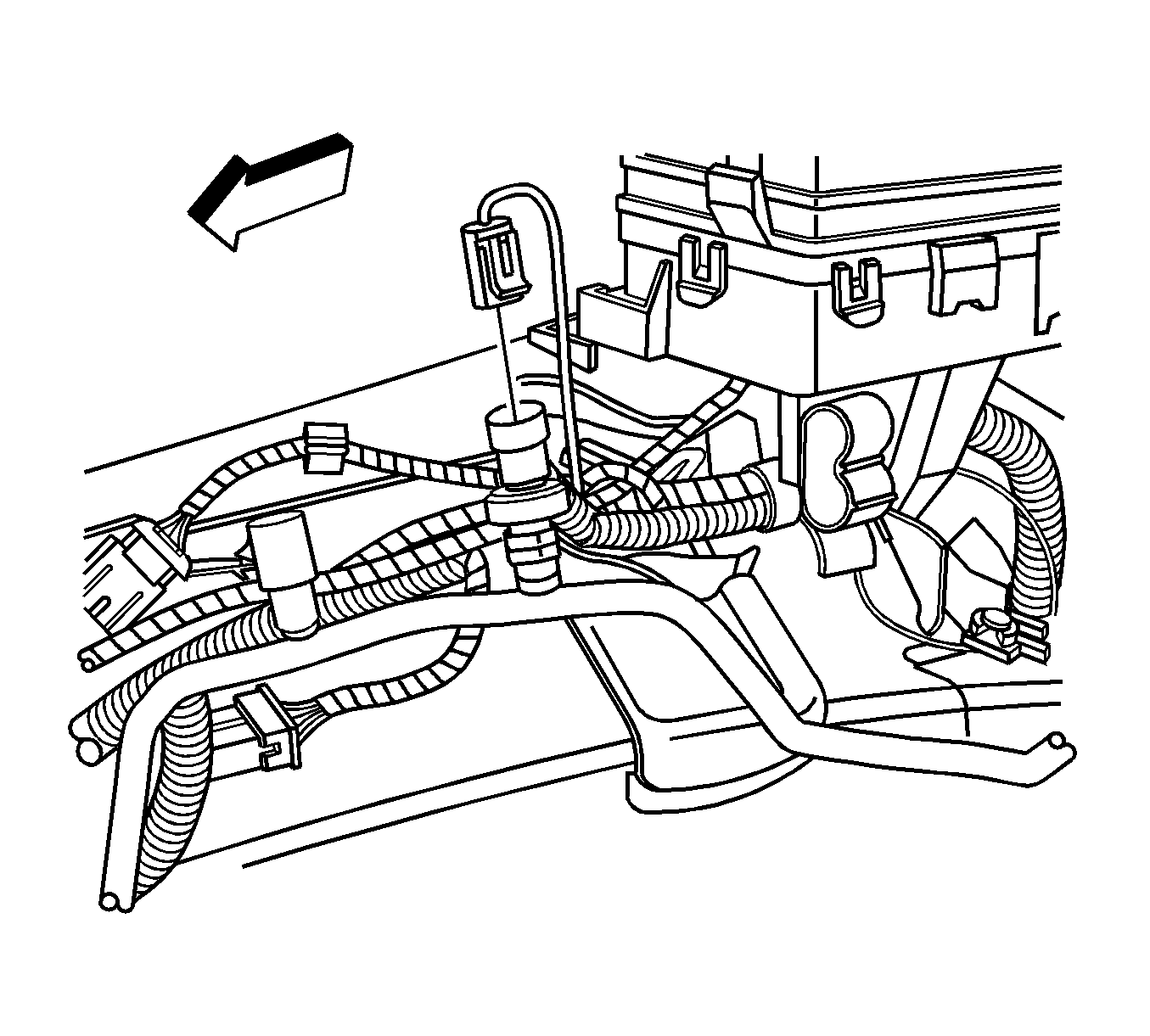
| • | The ECM--Refer to Engine Control Module Replacement. |
| • | The engine electrical harness--Refer to Underhood Electrical Center or Junction Block Replacement. |
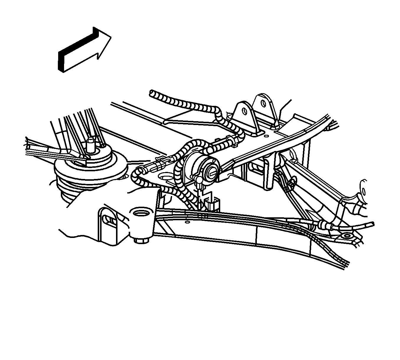
Installation Procedure
- Position the powertrain under the vehicle.
- With the aid of an assistant, slowly lower the vehicle onto the powertrain.
- Guide the front and rear cradle into the cradle bolts.
- Using HAND TOOLS ONLY, install the front and rear cradle nuts.
- Attach the transmission shift cable bracket to the transmission.
- Install the nuts retaining the transmission shift cable bracket to the transmission.
- Connect the transmission shift cable to the transmission shift lever.
- Install the transmission wiring harness to the left side of the transmission case retaining bolt.
- Connect the park/neutral position switch electrical connectors.
- Connect the wiring harness connectors to the bank 1 and bank 2 sensor 1 oxygen sensors. Refer to Heated Oxygen Sensor Replacement - Bank 1 Sensor 1 and Heated Oxygen Sensor Replacement - Bank 2 Sensor 1.
- Install the rear intermediate brake pipes into the clips.
- Install the driveline tunnel closeout panel.
- Install the bolts to the driveline closeout panel.
- Install the RH muffler assembly. Refer to Exhaust Muffler Replacement - Right Side.
- Install the LH muffler assembly. Refer to Exhaust Muffler Replacement - Left Side.
- Install the exhaust intermediate pipe. Refer to Intermediate Pipe Replacement.
- Connect the upper ball joint to the right knuckle. Refer to Knuckle Replacement.
- Install the rear shock absorber lower mounting bolts.
- Connect the road sensing suspension position link to lower control arm.
- Repeat for the other side of the vehicle.
- Connect the rear wheel speed sensor electrical connectors.
- Connect the rear park brake cables to the actuators. Refer to Parking Brake Rear Cable Replacement.
- Install the rear tire and wheel assemblies. Refer to Tire and Wheel Removal and Installation.
- Connect the upper ball joint to the right front suspension knuckle. Refer to Steering Knuckle Replacement.
- Install the shock absorber lower mounting bolts.
- Connect the road sensing suspension position sensor link to the front lower connect arm.
- Connect the front wheel speed sensor electrical connector.
- Repeat steps-through-for other side of vehicle.
- Install the master cylinder to the brake booster. Refer to Master Cylinder Replacement.
- Install the intermediate steering shaft to the steering column. Refer to Intermediate Steering Shaft Replacement.
- Connect the vacuum brake booster hose to the brake booster.
- Connect the heater hoses to the heater pipes. Refer to Heater Pipes Replacement.
- Connect the A/C lines to the front of dash connections. Refer to Air Conditioning Compressor Hose Replacement.
- Attach the engine ground cable to the right side body frame rail.
- Connect the following wiring harness electrical connectors:
- Install the right front wheelhouse panel. Refer to Front Wheelhouse Rear Liner Replacement.
- Install the front wheels and tires. Refer to Tire and Wheel Removal and Installation.
- Connect the UHJB to the wheelhouse.
- Connect the A/C electrical connector to the pressure sensor.
- Install the battery tray. Refer to Battery Tray Replacement.
- Install the battery. Refer to Battery Replacement.
- Install the air conditioning condenser. Refer to Air Conditioning Condenser Replacement.
- Install the radiator. Refer to Radiator Replacement.
- Install the surge tank. Refer to Radiator Surge Tank Replacement.
- Install the air cleaner assembly. Refer to Air Cleaner Assembly Replacement.
- Connect the fuel inlet quick-connect fitting to the fuel rail. Refer to Metal Collar Quick Connect Fitting Service.
- Connect the EVAP emission canister purge pipe (1) to the chassis purge pipe (2).
- Install the fuel injector sight shield. Refer to Fuel Injector Sight Shield Replacement.
- Charge the air conditioning (A/C) refrigerant. Refer to Refrigerant Recovery and Recharging.
- Connect the battery negative cable. Refer to Battery Negative Cable Disconnection and Connection.
- Program the transmitters. Refer to Transmitter Programming.
- Fill the crankcase with the proper quantity and grade of engine oil. Refer to Approximate Fluid Capacities and Fluid and Lubricant Recommendations.
- Reset the oil life monitoring system. Refer to GM Oil Life System Resetting.
- Perform the engine pre-lubrication procedures. Refer to Engine Prelubing.
- Start the engine.
- Run the engine speed at about 1,000 RPM until the engine has reached normal operating temperature.
- Inspect for fuel, oil, and/or coolant leaks while the engine is running.
- Perform a final inspection for the proper engine oil and coolant levels.
Notice: Refer to Fastener Notice in the Preface section.
Tighten
Tighten the nuts to 110 N·m (81 lb ft).

Tighten
Tighten the nuts to 20 N·m (15 lb ft).


Tighten
Tighten the transmission wiring harness to the left side of the transmission case retaining bolts to 2.5 N·m (22 lb in).


Tighten
Tighten the bolts to 10 N·m (89 lb in).

Tighten
Tighten the bolts to 28 N·m (21 lb ft).


Tighten
Tighten to 8 N·m (71 lb in).
| • | The ECM--Refer to Engine Control Module Replacement. |
| • | C101 engine electrical harness--Refer to Underhood Electrical Center or Junction Block Replacement. |


