Removal Procedure
- Remove the front brake lines. Refer to Front Brake Hose Replacement
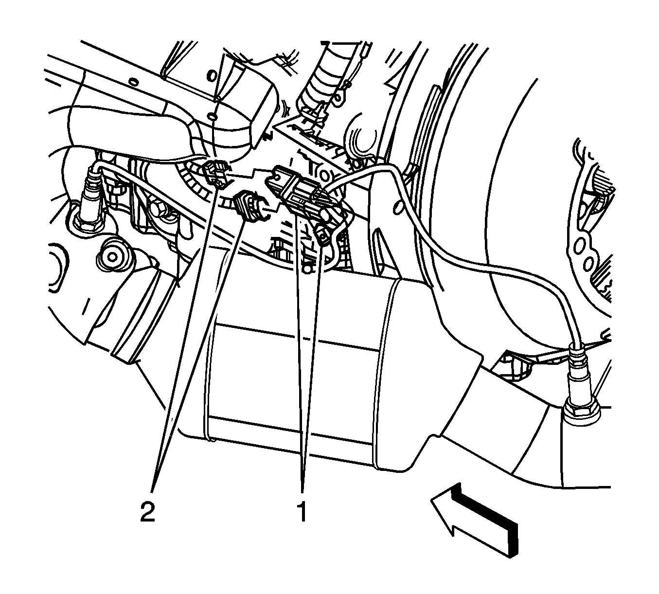
- Remove the connector position assurance (CPA) lock for the oxygen sensors.
- Disconnect the oxygen sensor electrical connectors (1, 2).
- Remove the oxygen sensors.
- Remove the powertrain. Refer to Powertrain Removal and InstallationPowertrain Removal and Installation.
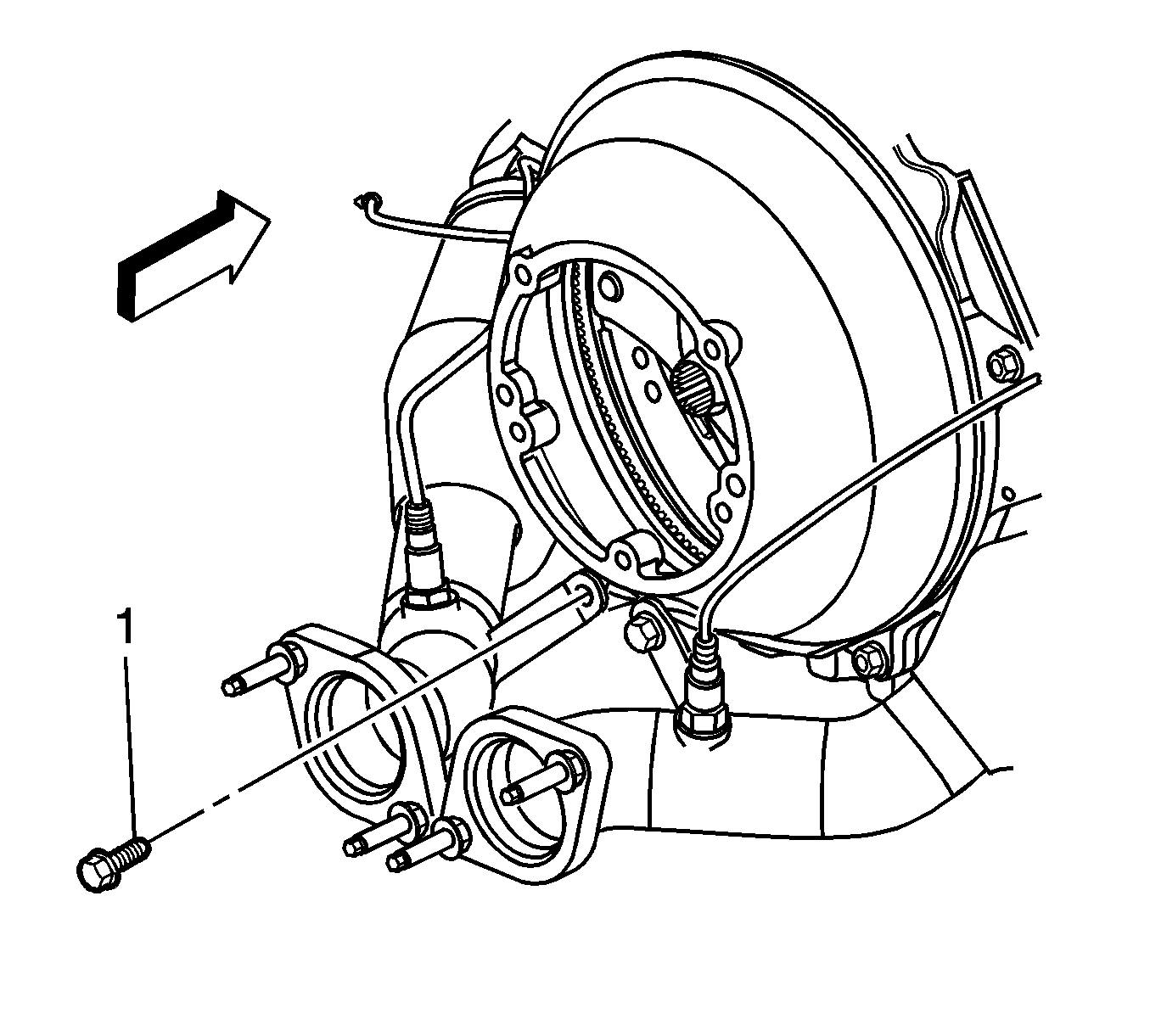
- Remove the exhaust manifold and catalytic converter assembly bolt securing the pipe to the bell housing.
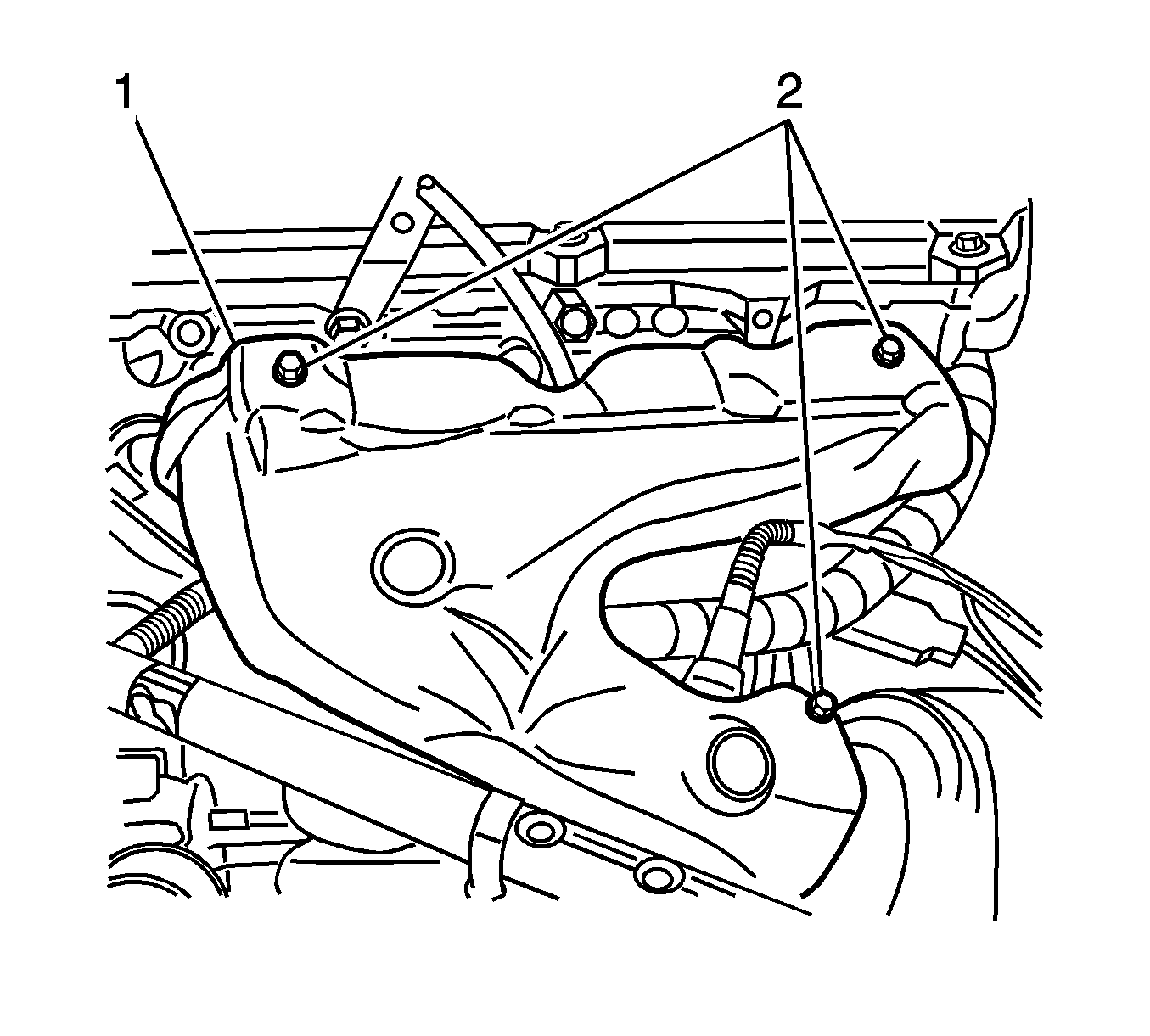
- Remove the left exhaust manifold heat shield bolts (2).
- Remove the left exhaust manifold heat shield (1).
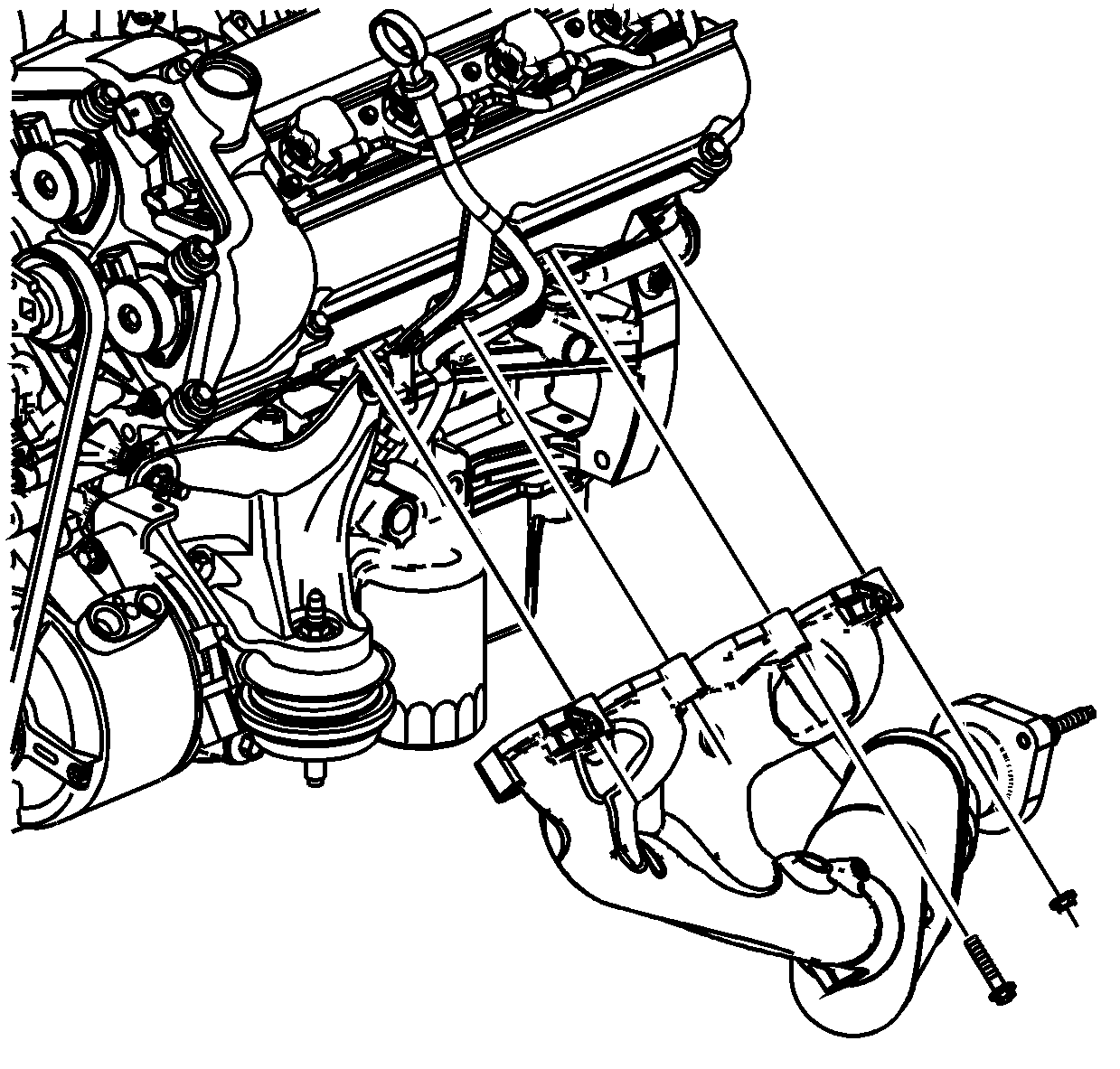
- Remove the exhaust manifold bolts and nuts.
- Remove the exhaust manifold.
- Remove the left exhaust manifold gasket.
- Discard the gasket.
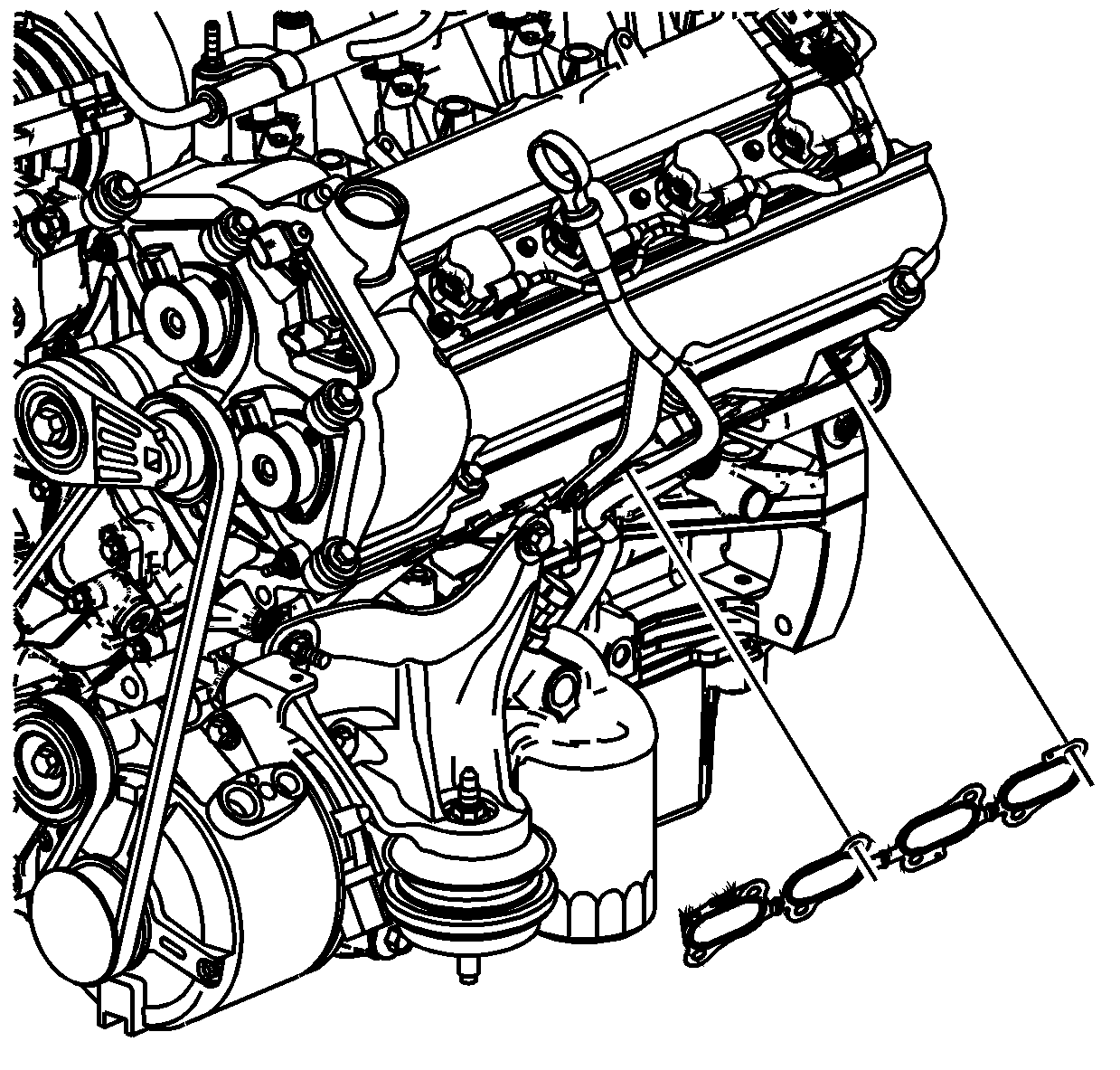
Installation Procedure
Important: Tighten the exhaust manifold bolts as specified in the service procedure. Improperly installed and/or leaking exhaust manifold gaskets may effect vehicle emissions and/or On-Board Diagnostics (OBD) II system performance.
The cylinder head exhaust manifold bolt hole threads must be cleaned and free of debris or threadlocking material.- Apply a 5 mm (0.2 in) wide band of threadlock GM P/N 12345493 (Canadian P/N 10953489), or equivalent to the threads of the exhaust manifold bolts and studs.
- Position the exhaust manifold and a NEW gasket into place.
- Install the exhaust manifold bolts and nuts.
- Install the exhaust manifold catalytic converter hanger bolt to the bell housing (1).
- Install the left exhaust manifold heat shield (1) and bolts (2).
- Apply anti-sieze compound GM P/N 12377953 or equivalent to the threads of the oxygen sensors.
- Install the oxygen sensors.
- Connect the oxygen sensor electrical connectors (2).
- Install the CPA locks (1).
- Install the powertrain. Refer to Powertrain Removal and Installation.


Notice: Refer to Fastener Notice in the Preface section.

Tighten
Tighten the exhaust manifold bolts and nuts to 25 N·m (18 lb ft). Tighten the exhaust manifold bolts and nuts beginning with the center two nuts. Alternate from side-to-side, working toward the outside
bolts and nuts.

Tighten
Tighten the exhaust hanger bolt to 50 N·m (37 lb ft).

Tighten
Tighten the exhaust manifold heat shield bolts to 10 N·m (89 lb in).
Notice: Refer to Oxygen Sensor Notice in the Preface section.
Tighten
Tighten the oxygen sensors to 42 N·m (30 lb ft).

